Showing posts with label network. Show all posts

Tuesday, February 4, 2014

Network Security and Privacy


  1. CCNA wireless study guide and labs
  2. CCNA Networking practice guide
  3. CCNA labs
  4. CCNA Study guide 
  5. Cisco e-books
  6. E-books Network security


 University of Texax at Austin

Syllabus

  • Basics of cryptography: cryptographic hash functions, symmetric and public-key encryption
  • Authentication and key establishment
  • Buffer overflow attacks
  • Web security
  • Internet worms, viruses, spyware
  • Spam, phishing, botnets, denial of service
  • TCP/IP and DNS security
  • Firewalls and intrusion detection systems
  • Wireless security

Monday, February 3, 2014

Determine the path between two hosts across a network

 Once you create an internetwork by connecting your WANs and LANs to a router, you'll need to configure logical network addresses, such as IP addresses, to all hosts on the internetwork so that they can communicate across that internetwork.

The term routing is used for taking a packet from one device and sending it through the network to another device on a different network. Routers don't really care about hosts—they only care about networks and the best path to each network. The logical network address of the destination host is used to get packets to a network through a routed network, and then the hardware address of the host is used to deliver the packet from a router to the correct destination host.
Eventually the packet reaches a router that is part of a network that matches the destination IP address of the packet. In this example, router R2 receives the packet from R1. R2 forwards the packet out its Ethernet interface, which belongs to the same network as the destination device, PC2.

Routers Operate at Layers 1, 2, and 3

A router makes its primary forwarding decision at Layer 3, but as we saw earlier, it participates in Layer 1 and Layer 2 processes as well. After a router has examined the destination IP address of a packet and consulted its routing table to make its forwarding decision, it can forward that packet out the appropriate interface toward its destination. The router encapsulates the Layer 3 IP packet into the data portion of a Layer 2 data link frame appropriate for the exit interface. The type of frame can be an Ethernet, HDLC, or some other Layer 2 encapsulation – whatever encapsulation is used on that particular interface. The Layer 2 frame is encoded into the Layer 1 physical signals that are used to represent bits over the physical link.

To understand this process better, refer to the figure. Notice that PC1 operates at all seven layers, encapsulating the data and sending the frame out as a stream of encoded bits to R1, its default gateway.

R1 receives the stream of encoded bits on its interface. The bits are decoded and passed up to Layer 2, where R1 de-capsulate the frame. The router examines the destination address of the data link frame to determine if it matches the receiving interface, including a broadcast or multicast address. If there is a match with the data portion of the frame, the IP packet is passed up to Layer 3, where R1 makes its routing decision. R1 then re-encapsulates the packet into a new Layer 2 data link frame and forwards it out the outbound interface as a stream of encoded bits.

R2 receives the stream of bits, and the process repeats itself. R2 de-capsulate the frame and passes the data portion of the frame, the IP packet, to Layer 3 where R2 makes its routing decision. R2 then re-encapsulates the packet into a new Layer 2 data link frame and forwards it out the outbound interface as a stream of encoded bits.

This process is repeated once again by router R3, which forwards the IP packet, encapsulated inside a data link frame and encoded as bits, to PC2.

Each router in the path from source to destination performs this same process of de-capsulation, searching the routing table, and then re-encapsulation. This process is important to your understanding of how routers participate in networks. Therefore, we will revisit this discussion in more depth in a later section.

Routing Table Principles


At times in this course we will refer to three principles regarding routing tables that will help you understand, configure, and troubleshoot routing issues. These principles are from Alex Zinin’s book, Cisco IP Routing.

1. Every router makes its decision alone, based on the information it has in its own routing table.

2. The fact that one router has certain information in its routing table does not mean that other routers have the same information.

3. Routing information about a path from one network to another does not provide routing information about the reverse, or return, path.

What is the effect of these principles? Let’s look at the example in the figure.

1. After making its routing decision, router R1 forwards the packet destined for PC2 to router R2. R1 only knows about the information in its own routing table, which indicates that router R2 is the next-hop router. R1 does not know whether or not R2 actually has a route to the destination network.

2. It is the responsibility of the network administrator to make sure that all routers within their control have complete and accurate routing information so that packets can be forwarded between any two networks. This can be done using static routes, a dynamic routing protocol, or a combination of both.

3. Router R2 was able to forward the packet toward PC2’s destination network. However, the packet from PC2 to PC1 was dropped by R2. Although R2 has information in its routing table about the destination network of PC2, we do not know if it has the information for the return path back to PC1’s network.

Metropolitan Area Network (MAN)

• A metropolitan area network (MAN) is a large computer network that usually spans a city or a large campus.
• A MAN is optimized for a larger geographical area than a LAN, ranging from several blocks of
buildings to entire cities.
• A MAN might be owned and operated by a single organization, but it usually will be used by many individuals and organizations
• A MAN often acts as a high speed network to allow sharing of regional resources.
• A MAN typically covers an area of between 5 and 50 km diameter.
• Examples of MAN: Telephone company network that provides a high speed DSL to customers and cable TV network.

Personal Area Network (PAN)

• A PAN is a network that is used for communicating among computers and computer devices (including telephones) in close proximity of around a few meters within a room
• It can be used for communicating between the devices themselves, or for connecting to a larger network such as the internet.
• PAN’s can be wired or wireless

Network Diagram Creation and Interpretation

 Figure with different nodes and edges is as follows;

As a network engineer, there will be a number of different times that a network diagram will be used to offer a layout of how the network is constructed and connected together. The knowledge of how to create and interpret these diagrams is vital in a number of different circumstances. This article is intended to be a primer on network diagrams, what the common symbols are, how the symbols are connected and how to interpret the different connectors on a diagram.

There are certainly a number of different things that a new network engineer needs to learn before being considered experienced. One of the most underrated skills is the ability to both create and understand network diagrams. As a network engineer, there will be a number of different times that a network diagram will be used to offer a layout of how the network is constructed and connected together. The knowledge of how to create and interpret these diagrams is vital in a number of different circumstances. One common task performed by new engineers is to troubleshoot reported issues; if these issues are related to the network, it is vital that an engineer look at the existing network diagrams and understand how traffic traverses the network. Any well-managed organization typically has a number of different diagrams that show everything from high level network connectivity to logical assignment diagrams showing the assigned IP addresses (or future assignments) on the network devices or segments. This article is intended to be a primer on network diagrams, what the common symbols are, how the symbols are connected and how to interpret the different connectors on a diagram.
Network Diagram Symbols

There are a number of different symbols that are common to network diagrams; on top of these common symbols there are some unique symbols that are created as different technologies evolve. This article takes a look solely at the most common symbols used; once these symbols become familiar, any new symbols that are encountered should be easy to interpret.
Bridges and Switches

There are a number of different devices that have the word switch in their name. These devices may have different functions but they are generally related with Layer 2 (data link) of the OSI network model. This can cause some confusion as some of these devices are not restricted on modern equipment to Layer 2, this will be discussed next.

A very common symbol is the one used for a simple Layer 2 LAN switch. This device is limited to processing frames at Layer 2; the symbol is shown in Figure 1:
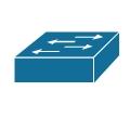


Figure1. SWITCH
Another symbol that can be seen on some older network diagrams is for a bridge; a bridge is a device that also forwards frames only at Layer 2; however a bridge predated switches and typically only had a few interfaces at most and was used to create separate collision domains. The symbol is shown in

FIGURE 2:bridge
Another form of a bridge that is more commonly seen these days is one that utilizes a wireless link to ‘bridge’ across a space that is not wired or is not easily wireable; this device is called a wireless bridge. The symbol used for a wireless bridge is shown in Figure 3.
X
Figure 3.:wireless bridge
A more modern version of a switch that is being more popular and thus more often seen in newer diagrams is a Layer 3 switch. A Layer 3 switch also handles Layer 2 frames like a ‘normal’ switch but also has the capability to process packets at Layer 3.The symbol for a Layer 3 switch is shown in Figure 4.


Figure 4 Layer 3 Switch
There are also a number of different devices that are not specific to a data network; one of these is an Integrated Services Digital Network (ISDN) switch. The symbol used for an ISDN switch is shown in Figure 5.

Figure 5 ISDN Switch

Finally, the last switch type discussed in this article is used for internal voice communications within a company; this device is often a Private Branch Exchange (PBX). The symbol used for a PBX is shown in Figure 6.
Figure 6 PBX
Routers


At least one router is a staple on most networks. This device is used to route any Layer 3 traffic (network) off of the local network onto another network, whether that be on another part of a company’s network or a simple Internet connection through DSL or Cable. The symbol used for a wired router is shown in Figure 7.
Figure 7 Router (Wired)


Another symbol which is commonly seen on modern networks is one that combines the capabilities of a router and a wireless access point; this device is commonly referred to as a wireless router. The symbol for a wireless router is shown in Figure 8.
Figure 8 Wireless Router


Another feature that is commonly combined with a router is voice; as with the wireless router there is a symbol that is used specifically for routers that also have voice capabilities; this symbol is shown in Figure 9.
Figure 9 Voice Router
Miscellaneous

There are a number of different popular symbols that fit into different categories; for the sake of this article we will throw them all into the same heading. The first of these is a generic PC; the symbol is shown in Figure 10.


Figure 10 PC

A common symbol on network diagrams that show connections with untrusted networks is a firewall; there are a number of different variations on a firewall symbol with the one shown here being a generic firewall. An image of something resembling bricks is often part of device symbols which combine function (i.e. IOS firewall). The symbol used for a generic firewall is shown in Figure 11.

Figure 11 Firewall

The last symbol that will be shown is for a voice telephone; with voice being more and more a part of a converged network, it is becoming more common for network diagrams to include both the data network elements and the voice network elements (as these services are being combined). The symbol used for a phone is shown in Figure 12.

Figure 12 Phone

An older device that is found on network diagrams is a hub; a hub is not typically seen that often on any modern networks, as most have been replaced by switches. The symbol for a hub is shown in Figure 13.

Figure 13 Hub
Network Diagram Connectors

There are a number of different ways that connections can be shown within a diagram; generally speaking, there are four major ways to show connections. The first of these is a simple line, as all people are familiar with what a line looks like an image is not required. A line can signify any technology and the type of link typically relies on the devices being connected and/or text that are commonly combined with the line.

The second of these is a comm. link or WAN link; these connectors are used to signify that a connection is a WAN technology. For example, the link could be Frame Relay, ATM, MPLS or a number of different WAN technologies; again, the specific type of link is derived from the types of devices being connected and any accompanying text. The symbol used for a comm./WAN link is shown in Figure 14.

Figure 14 WAN Link

Another common symbol that is used in combination with other connector types is that for a ‘cloud’; the ‘cloud’ can represent a number of different things including the Internet, a Frame Relay network, and a provider’s network, among others. A symbol for a ‘cloud’ is shown in Figure 15.
Figure 15 Cloud

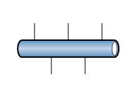
The last symbol that will be discussed is for an Ethernet network; this symbol is often used in more detailed Ethernet diagrams to represent specific Ethernet segments. The symbol for an Ethernet network is shown in Figure 16.

Network Diagram Creation and Interpretation
Figure 16 Ethernet Network

Wide Area Network (WAN)

Wide Area Network (WAN)
• WAN covers a large geographic area such as country, continent or even whole of the world.
• A WAN is two or more LANs connected together. The LANs can be many miles apart.
• To cover great distances, WANs may transmit data over leased high-speed phone lines or wireless links such as satellites.
• Multiple LANs can be connected together using devices such as bridges, routers, or gateways, which enable them to share data.
• The world's most popular WAN is the Internet

Advantage and Disadvantages of LAN

Advantage of LAN

• Speed
• Cost
• Security
• E-mail
• Resource Sharing

Disadvantages of LAN

• Expensive To Install
• Requires Administrative Time
• File Server May Fail
• Cables May Break

Local Area Network LAN

• A LAN is a network that is used for communicating among computer devices, usually within an office building or home.
• LAN’s enable the sharing of resources such as files or hardware devices that may be needed by multiple users
• Is limited in size, typically spanning a few hundred meters, and no more than a mile
• Is fast, with speeds from 10 Mbps to 10 Gbps
• Requires little wiring, typically a single cable connecting to each device
• Has lower cost compared to MAN’s or WAN’s
• LAN’s can be either wired or wireless. Twisted pair, coaxial or fibre optic cable can be used in wired LAN’s.
• Every LAN uses a protocol – a set of rules that governs how packets are configured and transmitted.
• Nodes in a LAN are linked together with a certain topology. These topologies include:
– Bus
– Ring
– Star
• LANs are capable of very high transmission rates (100s Mb/s to G b/s).

Advantage of LAN

• Speed
• Cost
• Security
• E-mail
• Resource Sharing

Disadvantages of LAN

• Expensive To Install
• Requires Administrative Time
• File Server May Fail
• Cables May Break

Network application

A computer network or data network is a telecommunications network that allows computers to exchange data. In computer networks, networked computing devices pass data to each other along data connections. The connections (network links) between nodes are established using either cable media or wireless media. The best-known computer network is the Internet.
Network computer devices that originate, route and terminate the data are called network nodes.[1] Nodes can include hosts such as servers and personal computers, as well as networking hardware. Two devices are said to be networked when a device is able to exchange information with another device.
Computer networks support applications such as access to the World Wide Web, shared use of application and storage servers, printers, and fax machines, and use of email and instant messaging applications. Computer networks differ in the physical media used to transmit their signals, the communications protocols to organize network traffic, the network's size, topology and organizational intent.


 Sample applications

• E-mail
• Web
• Instant messaging
• Remote login
• P2P file sharing
• Multi-user network games
• Streaming stored video clips
• Internet telephone
• Real-time video conference
• Massive parallel computing

Typical architectures

• Client-server
• Peer-to-peer (P2P)
• Hybrid of client-server and P2P

FUNCTION OF TCP LAYER


The TCP/IP model was not created by a standards developing committee but rather from research funded by the Department of Defense (DOD) Advanced Research Projects Agency (ARPA). ARPA begin working on TCP/IP technology in the mid 1970s with the protocols and architecture taking on their current structure in the 1977-1979 time frame.

TCP/IP Protocol Stack Layers

The TCP/IP protocol stack is organized into four layers as shown in Figure 2-3. Each of the four layers of the TCP/IP model exists as an independent module and performs a well-defined function as described later in this section. Each layer communicates and works with the functions of the layers that are immediately above and below it. For example, looking at Figure 2-3 you see that the Transport layer sits between the Application and Internet layers. This means that the Transport layer will communicate and work with both the Application and Internet layers. The Transport layer cannot communicate directly with any other layer of the TCP/IP model.

Figure 3: TCP/IP Protocol Stack

TCP/IP Application Layer

The Application layer is the highest layer in the TCP/IP model. It is used by applications to access services across a TCP/IP network. Some of the applications that operate at this layer are a Web browser, file transfer program (FTP), and a remote login program. The Application layer passes data to the next layer in the stack, the Transport layer.

TCP/IP Transport Layer

The Transport layer is located at layer 3 of the TCP/IP model. The main responsibility of the Transport layer is to provide communication from one application to another application. If several application programs are running on a computer then the Transport layer has to figure out how to control the data from each application so that it can be sent to the next lower layer correctly. The Transport layer adds the following additional information to each data packet:
The identity of the application sending the data
The identity of the application that should receive the data
A checksum
The system that receives the data uses the checksum to verify that all of the data arrived. It also uses the identity of the receiving application so it can route the data appropriately.

TCP/IP Internet Layer

The Internet layer is located at layer two of the TCP/IP model. It is responsible for handling the communication from one computer to another computer. It accepts a request to send data from the Transport layer. It accepts the data, encapsulates it in a datagram, and then uses a routing algorithm to determine the best method for delivering it. After determining the best way to route the datagram, the Internet layer passes it to the Network Interface layer.

TCP/IP Network Interface Layer

The Network Interface layer is the lowest level in the TCP/IP model. It accepts the datagram from the Internet layer and transmits it over the network. To accomplish this task the Network Interface layer must be fully aware of the network hardware that it is using. The Network Interface layer is also responsible for translating an Internet address into a hardware address.
Exam Watch: Remember the names and functions of each of the four layers of the TCP/IP model.

TCP/IP Protocol Stack Compared to OSI Layers

The TCP/IP model can be compared loosely to the OSI model as shown in Figure 2-4. The Application layer of the TCP/IP model performs the same functions as layers 5, 6, and 7 of the OSI model. The Transport layers in both models perform the same functions. The Internet layer of the TCP/IP model equates to the same functions as the Network layer of the OSI model. The Network Interface layer of the TCP/IP model compares to the functions of layers 1 and 2 of the OSI model.

Figure 4: TCP/IP Model Compared to OSI Model
Exam Watch: Remember which layers of the TCP/IP model equate to the layers of the OSI model.

TCP/IP Protocol Suite

Contained within the four layers of the TCP/IP model are several protocols that direct how computers connect and communicate using TCP/IP. Even though the protocol suite is called TCP/IP, many other protocols are available besides the TCP and IP protocols.

Identify Protocols by Layers

Each protocol can be identified with a layer of the TCP/IP model. We will examine several of the protocols available at each layer.

Application Layer

The Application layer supports both the NetBIOS interface and the Windows Sockets interface.

NetBIOS

NetBIOS over TCP/IP allows NetBIOS client and server applications to be run over the Wide Area Network (WAN). Some of the applications that are NetBIOS-over -TCP compliant are the Windows NT browser service, netlogon service, messenger service, workstation service, and server service.

Windows Sockets

Windows Sockets is a programming interface based on the "socket" interface that was originally developed at the University of California at Berkeley. Windows Sockets includes enhancements that take advantage of the message-driven characteristics of Windows. Windows NT 4.0 supports version 2.2.0, which was published in May 1996. Some of the common protocols that use Windows Sockets are telnet, ftp, and http.

Transport Layer

The Transport layer consists of two protocols, the Transmission Control Protocol (TCP) and the User Datagram Protocol (UDP). Both TCP and UDP support ports. When a program sends or receives data on a TCP/IP network, it has to connect to a port. Ports are identified in the header of both the TCP and UDP protocols. The header contains two 16-bit numbers that identify the source port and the destination port. The Transport layer examines the port numbers in the header and delivers the data to the correct port.

TCP

TCP is one of the protocols that the suite is named for. TCP provides a reliable, connection-based delivery service. Successful delivery of packets is guaranteed by the TCP protocol. It uses a checksum to ensure that data is sequenced correctly. If a TCP packet is lost or corrupted during transmission, TCP resends a good packet. The reliability of TCP is necessary for critical services, such as electronic mail. However, the reliability does not come cheaply as TCP headers have additional overhead added to them. The overhead is necessary to guarantee successful delivery of the data. Another factor to remember about TCP is that the protocol requires the recipient to acknowledge the successful receipt of data. Of course, all the acknowledgments, known as ACKs, generate additional traffic on the network, which causes a reduction in the amount of data that is passed for a given time frame.
The TCP header consists of six words of 32 bits each. The seventh word is the actual data. Figure 2-5 shows the format of a TCP header.

Figure 5: Transmission Control Protocol Header
Table 2-1 describes each of the items that are contained in the TCP header.
Name
Bit Size
Purpose
Source Port
16
The source port number.
Destination Port
16
The destination port number.
Sequence Number
32
The sequence number of the first data octet in this segment unless the SYN control bit is set. If the SYN control bit is set, then the sequence number is the initial sequence number (ISN) and the first data octet is ISN+1.
Acknowledgment Number
32
This portion of the header contains the value of the next sequence number that the sender of the segment is expecting to receive if the ACK control bit is set. Once a connection is established, this is always sent.
Data Length
4
The number of 32-bit words in the TCP header. This indicates where the data begins.
Reserved
6
Reserved for future use. It has to be zero.
Flags
6
The bits from left to right.URG: Urgent Pointer field significant
ACK: Acknowledgment field significant
PSH: Push function
RST: Reset the connection
SYN: Synchronize sequence numbers
FIN: No more data from sender
Window
16
The number of data octets beginning with the one indicated in the acknowledgment field, which the sender of this segment is willing to accept.
Checksum
16
The checksum field is the 16-bit 1’s complement of the 1’s complement sum of all 16-bit words in the header and data.
Urgent Pointer
16
This field communicates the current value of the urgent pointer as a positive offset from the sequence number in this segment. The urgent pointer points to the sequence number of the octet following the urgent data. This field is interpreted only in segments that have the URG control bit set.
Options
variable
Options may occupy space at the end of the TCP header and are a multiple of 8 bits in length. All options are included in the checksum.
Padding
variable
The TCP header padding is used to ensure that the TCP header ends and data begins on a 32-bit boundary. The padding is composed of zeros.
Table 1: Description of the Contents in a TCP Header

UDP

UDP offers a connectionless datagram service that is an unreliable "best effort" delivery. The arrival of datagrams is not guaranteed by UDP nor does it promise that the delivered packets are in the correct sequence. Applications that don’t require an acknowledgment of receipt of data use the User Datagram Protocol.
The UDP header consists of two words of 32 bits each. The third word is the actual data. Figure 2-6 shows the format of a UDP header.

Figure 6: User Datagram Protocol Header
Table 2-2 describes each of the items that are contained in the UDP header.
Name
Bit Size
Purpose
Source Port
16
The source port number.
Destination Port
16
The destination port number.
Length
16
The length in octets of this user datagram including the header and data.
Checksum
16
The checksum field is the 16-bit 1's complement of the 1's complement sum of all 16-bit words in the header and data. The checksum is an option in the UDP header and not always used.
Table 2: Description of the Contents in a UDP Header
Exam Watch: Keep in mind the key differences between the Transmission Control Protocol and User Datagram Protocol.

Internet Layer

The Internet layer consists of two protocols, the Internet Protocol (IP) and the Internet Control Message Protocol (ICMP).

IP

IP is the other protocol that the suite is named for. It is a vital link in the suite as all information that is sent using the TCP/IP protocol suite must use it. IP provides packet delivery for all other protocols within the suite. It is a connectionless delivery system that makes a "best-effort" attempt to deliver the packets to the correct destination. IP does not guarantee delivery nor does it promise that the IP packets will be received in the order they were sent. IP does use a checksum but it confirms only the integrity of the IP header. Confirmation of the integrity of data contained within an IP packet can be accomplished only through higher level protocols.
The IP header consists of six words of 32 bits each. The seventh word is the actual data. Figure 2-7 shows the format of a IP header.

Figure 7: Internet Protocol Header
Table 2-3 describes each of the items that are contained in the IP header.
Name
Bit Size
Purpose
Version
4
The format of the Internet header.
IHL
4
Internet header length is the length of the Internet header in 32-bit words. The minimum value for a correct header is 5.
Type of Service
8
An indication of the abstract parameters of the quality of service desired.
Total Length
16
The length of the datagram, measured in octets, including Internet header and data.
Identification
16
An identifying value assigned by the sender to aid in assembling the fragments of a datagram.
Flags
3
Various control flags.Bit 0: reserved, must be zero
Bit 1: (DF) 0 = may fragment, 1 = don't fragment.
Bit 2: (MF) 0 = last fragment, 1 = more fragments.
Fragment Offset
13
Indicates where in the datagram this fragment belongs. The fragment offset is measured in units of 8 octets (64 bits). The first fragment has offset zero.
Time to Live
8
Indicates the maximum time the datagram is allowed to remain in the Internet system. If this field contains the value zero, then the datagram has to be destroyed.
Protocol
8
Indicates the next level protocol used in the data portion of the Internet datagram.
Header Checksum
16
A checksum on the header only. Since some header fields change, such as the time-to-live field, this is recomputed and verified at each point that the Internet header is processed.
Source Address
32
The source address.
Destination Address
32
The destination address.
Options
variable
The options may or may not appear in datagrams. A couple of the available options are:Security: used to carry security, compartmentation, and handling restriction codes compatible with DOD requirements.
Record Route: used to trace the route an Internet datagram takes.
Padding
variable
The Internet header padding is used to ensure that the Internet header ends on a 32-bit boundary. The padding is zero.
Table 3: Description of the Contents in a IP Header

ICMP

ICMP allows systems on an TCP/IP network to share status and error information. You can use the status information to detect network trouble. ICMP messages are encapsulated within IP datagrams, so they may be routed throughout an internetwork. Two of the most common usages of ICMP messages are ping and tracert.
You can use ping to send ICMP Echo Requests to an IP address and wait for ICMP Echo Responses. Ping reports the time interval between sending the request and receiving the response. Using ping you can determine whether a particular IP system on your network is functioning correctly. There are many different options that can be used with the ping utility. These are covered in depth in Chapter 3.
Tracert traces the path taken to a particular host. It can be very useful when troubleshooting internetworks. Tracert sends ICMP echo requests to an IP address while it increments the time-to-live field in the IP header by a count of one after starting at one and then analyzing the ICMP errors that get returned. Each succeeding echo request should get one further into the network before the time-to-live field reaches 0 and an ICMP Time Exceeded error is returned by the router attempting to forward it.
Exercises 2-1 and 2-2 give you the opportunity to use both the PING and TRACERT utilities.
Exercise 2-1 Ping – to Test Communication with a Distant Computer
  1. Log on as Administrator to a system that has the TCP/IP Protocol installed and is connected to the Internet.
  2. Click the Start button and select Programs | Command Prompt.
  3. At the command prompt type PING 207.159.134.58. Was your PING successful?
  4. Try to PING some of these other IP addresses: 206.66.12.43, 165.121.81, 206.151.75.79, 199.1.11.15, 199.227.250.70. Did you PING them successfully?
Exercise 2-2 Tracert – to Trace the Route Taken to a Distant Computer
  1. Log on as Administrator to a system that has the TCP/IP Protocol installed and is connected to the Internet.
  2. Click the Start button and select Programs | Command Prompt.
  3. At the command prompt type TRACERT 207.159.134.58. How many hops did it take to arrive at your destination?
  4. Try running TRACERT on some of these other IP addresses: 206.66.12.43, 165.121.81, 206.151.75.79, 199.1.11.15, 199.227.250.70.

Network Interface Layer

The Network Interface layer not only uses the Address Resolution Protocol (ARP) but it is also the location that the Network Driver Interface Specification (NDIS) 4.0 works from.

ARP

ARP is used to provide IP address-to-physical address resolution for IP packets. To accomplish this feat, ARP sends out a broadcast message with an ARP request packet in it that contains the IP address of the system it is trying to find. All systems on the local network detect the broadcast message and the system that owns the IP address ARP is looking for replies by sending its physical address to the originating system in an ARP reply packet. The physical/IP address combo is then stored in the ARP cache of the originating system for future use.
All systems maintain an ARP cache that includes their own IP address-to-physical address mapping. The ARP cache is always checked for an IP address-to-physical address mapping before initiating a broadcast.
You can see the contents of your ARP cache by using the ARP utility. There are many different options that can be used with the ARP utility. These are covered in depth in Chapter 3. Exercise 2-3 shows you how to check the contents of your ARP cache.
Exercise 2-3 ARP – To view What Is in the Address Table
  1. Log on as Administrator to a system that has the TCP/IP Protocol installed.
  2. Click the Start button and select Programs | Command Prompt.
  3. At the command prompt type ARP -a. The entries in your cache are displayed.
Figure 2-8 shows entries in the ARP cache of my system.

Figure 8: The ARP Cache for a System

NDIS 4.0

NDIS is a standard that allows multiple network adapters and multiple protocols to coexist on the same computer. By providing a standard interface, NDIS permits the high-level protocol components to be independent of the network interface card. All transport drivers call the NDIS interface to access network interface cards.
Figure 2-9 shows a sampling of the protocols available on the four TCP/IP layers.

Figure 9: Protocols by TCP/IP Layers
Now that you know about the different protocols used by the TCP/IP layers, here is a quick reference for possible scenario questions, and the appropriate answer:
Begin Q & A
"Marissa says that it take her "forever" to reach a host in another city…" Use TRACERT to see the path her machine may be using to contact the other machine. You may be able to isolate a routing problem.
"Martha is having a problem with inconsistent data she is receiving from a network application…" It is possible that the network application uses UDP instead of TCP. Since UDP provides unreliable "best effort" delivery, some data may be lost. You need to see if you can get her an equivalent network application that uses TCP to ensure that all data she needs arrives safely.
"James from the sales department tells you that he cannot communicate with a machine in the accounting department…" You need to run the PING utility to see if the computer is operating correctly on the network.

Network Data Flow

In the previous sections, we have seen the layers that make up the OSI and TCP/IP models and the purpose of each of those layers. Now it is time to see what happens as data begins to flow from one layer to the next.

How A Message Flows Through the TCP/IP Protocol Layers

The sending process passes data to the Application layer, which attaches an application header as shown in Figure 2-10.

Figure 10: Data Passed to the Application Layer
The Application layer passes the packet to the Transport layer, which in turn adds its header to the packet as shown in Figure 2-11.

Figure 11: Application Data Passed to the Transport Layer
The Transport layer passes the packet to the Internet layer, which in turn adds its header to the packet as shown in Figure 2-12.

Figure 12: Transport Data Passed to Internet Layer
The Internet layer passes the packet to the Network Interface layer where it is actually transmitted to the receiving computer as shown in Figure 2-13.

Figure 13: Data Leaving the Network Interface Layer, Headed to the Receiving Computer
On the receiving computer, the different headers are stripped off, one by one, as the packet goes up the layers until it finally reaches the receiving process.

Sunday, February 2, 2014

[ COMPUTER NETWORK ] Error Detection and Correction

3.2 Error Detection and Correction

Error detection is generally cheaper (in terms of additional bits in overhead) to do than error correction. Neither are always needed, audio and video can often have some errors without noticeably affecting the perceived transmission quality. Error detection makes sense whenever the data must be absolutely reliable (an ATM cash machine transaction) or when the medium is very error prone (phone lines, wireless). Error correction is reasonable when retransmitting the data is not feasible (e.g. a probe designed to crash land on Saturn) or very expensive. Much of the current practice in error detection and correction is based on work by the mathematician Hamming. Applications include not only data transmission but data storage (e.g. use of a checksum to verify data integrity on a storage device).
3.2.1 Error Correcting Codes - Codes that allow the original data to be reconstructed in the face of incurring one or more errors. Generally the more errors that can be corrected, the larger the correcting code required (in bits).
  • Code word - A data frame generally consists of:
    • m data bits (message)
    • r code bits
    • m + r = n bit code word.
  • Hamming distance -  The number of bit positions two code words differ. 000 and 111 have a Hamming distance of 3, 101 and 000 have a distance of 2. The XOR (eXclusive OR) of two code word bits determines number of bits different. For example,
       100010
XOR 011010
       111000    Distance = 3   
A B | A xor B
0 0 |    0
0 1 |    1
1 0 |    1
1 1 |    0
    Significant in that for two codewords d distance apart, d single-bit errors can convert one to the other. For a distance of 1 a single error could convert one codeword into another, for example:
    000000 is a distance of 1 from 000001, a single error changes 000000 to 000001
What is the Hamming distance between 000000 and 111100?
    Parity Example
    No parity

      Even parity


    00   m=2, r=0, d=1
    000 valid   m=2, r=1, d=2
    01
    The change of any one
    001 invalid
    Adding parity doubles
    10
    bit results in a valid
    010 invalid
    the number of codewords, but 
    11
    codeword. No error 
    011 valid
    only half are valid. Any single bit


    can be detected.
    100 invalid
    error produces an invalid code.


    101 valid


    110 valid


    111 invalid

  • What is the odd parity for the ASCII data: 11111111 and 11111110?
  • Is data and parity bit 111100001 valid for even parity?
  • Suppose that one million bits were sent with a single parity bit for error detection. Would a 1-bit error be detected? Would all errors in two bits be detected?
  • Error correcting codes - To correct d errors requires a distance of 2d+1. d errors transform the codeword sent to one that is still one bit closer to the original than any other possible legal codes. The following codewords have a distance of 3, so a one bit error can be corrected. For example, if 000000 was sent and one error occurs, 100000 might be received. The closest codeword to 100000 is the original 000000 so could be corrected. Two errors might result in 110000 which would be closer to 111000, leading to an erroneous correction.
    Codewords for correcting a 1-bit error
    000000
    000111
    111000
    111111
  • What was sent if 000011 is received and we assume a 1-bit error occurred?
  • How many errors occurred at a minimum if 011001 is received? Can it be corrected reliably? Then what to do on receiving 000011?
  • Error correcting code construction - We want to construct an error correcting code with minimum check bits as overhead. For single bit error correction the limit for:
  • m data bits
  • r check bits
  • m+r+1 <= 2r
  • r=3 can correct one error in m=4 data bits, since m+3+1<=23 = 8, or m=4. 
  • r=4 can correct one error in m=11 data bits, since m+4+1<=24 = 16, or m=11. 
  • r=5 can correct one error in m=26 data bits, since m+5+1<=25 = 32, or m=26. 
The following is an example of a method by Hamming for constructing a minimal single bit error correcting code. The code has m=4 data bits, thus can encode 16 data values (00002-11112), and r=3 check bits. There are seven bits numbered from 1 to 7 with four data bits (m3, m2, m1, m0) and three check bits (p2, p1, p0). Note that check bits are placed at positions numbered as a power of 2 (e.g. check bit p2 is at position 4 = 22) between data bits. Data bits can be in any order but below are arranged in standard high bit at left order. The m data (m3m2m1m0) and r check bits (p2p1p0) are then organized into a vector as follows:
POSITION 1 2 3 4 5 6 7
BIT  p0  p1 m3 p2 m2 m1 m0
Data bits are checked by check bits whose position sum is equal to the position of the data bit. In this example:
m3 = p0 + p1            Position of m3 = Position of p0 + Position of p1 = 3
m2 = p0 + p2              Position of m2 = Position of p0 + Position of p2 = 5
m1 = p1 + p2              Position of m1 = Position of p1 + Position of p2  = 6
m0 = p2  + p1 + p0    Position of m0 = Position of p2 + Position of p1 + Position of p0 =7
    The p check bit values are computed from the data bits by forming the Exclusive-OR of all data bits checked by that bit as follows (note xor here is Exclusive OR):
    p2 = m2 xor m1 xor m0 
    p1 = m3 xor m1 xor m0
    p0 = m3 xor m2 xor m0
    Note that the sender computes p0, p1, p2.
    For example: p2 = m2 xor m1 xor m0 = 1 xor 0 xor 0 = 1
    The receiver can then perform the same calculation for the p check bits and if any differ a transmission  error occurred.
    Error position vector: The binary representation of the error position is given by the vector (C2, C1, C0), where:
    C0 = p0 xor m3 xor m2 xor m0

    C1 = p1 xor m3 xor m1 xor m0

    C2 = p2 xor m2 xor m1xor m0
    Note that the receiver computes C0, C1, C2.
    From the above computation of p2 = 1 and
    no errors in p2, m2, m1, m0
    C2 = p2 xor m2 xor m1xor m0 = 1 xor 1 xor 0 xor 0 = 0

    Example: The sender would compute the check bits and transmit both data and check bits as in the vector above. The receiver would compute the error position vector using the received data and check bit vector. For example, to send data 11002 the vector transmitted would be 01111002. Should a one bit error occur in position 4 the received vector would be 01101002.
POSITION 1 2 3 4 5 6 7
BIT  p0  p1 m3 p2 m2 m1 m0
TRANSMIT 0 1 1 1 1 0 0
RECEIVED 0 1 1 0 1 0 0
Computing the error vector yields (1, 0, 0) indicating that POSITION 4 (410 = 1002 of the received frame is in error and should be inverted to correct the error. 
    C0 = 0 xor 1 xor 1xor 0 = 0
    C1 = 1 xor 1 xor 0 xor 0 = 0
    C2 = 0 xor 1 xor 0 xor 0 = 1
3.2.2 Error Detecting Codes - To detect d errors requires a distance of d+1, no d number of  errors can change a valid code into another valid code.
    Parity
    The ASCII code uses 8 data bits, so that all possible valid 8-bit codes are used. The distance is one, since each valid code is 1 bit from another valid code. Hence one error transforms any valid code to another valid code.
    ASCII code with parity, 8 data bits and 1 bit parity for error checking has a distance of two, meaning each valid code + parity is at least 2 bits different from any other valid code. All valid codes are transformed by a 1 bit error into an invalid code. The invalid code is detected as an error.
    Using even parity (there is an even number of 1 bits in the data and parity bit) the letter A=00100001 0 (the last bit is parity calculated by the sender). A 1-bit error anywhere in data or parity will transform the codeword to an invalid code. Suppose the parity is changed from 0 to 1, then the received code is 00100001 1. The receiver calculates the parity and recognizes the codeword to be invalid so an error occurred somewhere in the data or parity.
    Note that more than one error has only a 50% chance of detection. For 11110000 0 sent, two errors could produce 11000000 0 which is still a valid code and would not be detected as an error by the receiver. Three errors producing 10000000 0 would be detected. Four errors producing 11000011 0 would not, etc. An odd number of bit errors is detected.
It is generally cheaper to detect an error and retransmit data than to send error correcting codes.
Sending 1,000,000 data bits in frames of 1000 bits using error correcting Hamming codes requires 10 check bits per 1000 data bit frames or 10,000 extra bit to correct single bit errors, a total of 1,010,000 bits transmitted (i.e. m+r+1 <= 2r or 1000+10+1=1011<= 210=1024).
  • Alternatively, 20 check bits could correct a 1 bit error for 1,000,000 data bits for a total of 1,000,020 bits (i.e. m+r+1 <= 2r or 1,000,000+20+1<= 220=1,048,576). Why is this a bad idea?
  • A single parity bit can detect one error in a 1,000,000 bit message but the message would be retransmitted when an error was detected. Under what conditions is this a bad idea or a good idea?
Using error detection and retransmit on a detected error requires 1 parity bit per 1000 data bits or 1000 check bits for the data plus 1 additional check bit for the 1000 parity bits, a total of 1,001,001 bits transmitted error free. For 1 error per million bits, error detection and retransmit requires 1,002,002 bits to be transmitted (i.e. an additional 1001 bits retransmitted).
One key problem is the lack of robustness to error detection using parity as it can detect 100% of single bit errors but only 1/2 of more than 1 bit errors. This can be improved by observing that most errors occur in bursts and reorganizing how blocks of data are sent.
Suppose that we send two 3 bit numbers 101 and 001 with even parity, 1010 and 0011. Sending as 1010 0011, a two bit error burst might transform the underlined bits to 1100 0011 which is not detected as an error by a parity check bit. Instead of sending all of one message data bits and parity bit at once which can only detect a one bit error, a more robust approach sends the first bit of each message, then the second, etc. This provides error detection of a 2 bit burst since only one bit in each column would be changed but not any 2 bit error, better than before but not good enough. The data and parity of both is sent as:
 
10  First bit
00  Second bit
11  Third bit
01  parity
Sending 1010 0011 would be transmitted as: 10001101. A two bit error burst in the underlined bits would be received as 10111101.
A two bit error burst, such as in the underlined bits, would be detected by the parity bits when the message was reconstructed by the receiver. In general, n frames with a parity bit can detect a single n bit error burst.
  •  Polynomial codes - CRC (cyclic redundancy check) codes can be constructed that provide significantly better error detection than parity. The sender computes a checksum sent with the data. The receiver recomputes the checksum on the received data using the same method, if the received and computed checksums differ, an error has been detected, retransmit the data. 
  • The method is roughly based on:
    1. Divide the data by an agreed upon divisor, the remainder is the checksum.
    2. Transmit the data and checksum remainder.
    3. Divide the received data by the agreed upon divisor. The computed and received remainder should be equal.
  • The method is straightforward and is illustrated below by an example.
    1. Convert data to binary: 'a'=61h=01100001
      M(x)=0x7+1x6+1x5+0x4+0x3+0x2+0x1+1x0 = 01100001
    2. To compute checksum, divide data M(x) by a selected generator polynomial G(x). Append 0 bits to M(x) for the degree of G(x).
      G(x)=x4+x+1 = 10011
      xrM(x) = 01100001  0000                M(x)          xr
    3. Divide xrM(x) by G(x) to get checksum, the remainder R(x). Use Exclusive OR rather than binary subtraction where a divisor divides the dividend if the same number of bits.
               Q(x) 
      G(x)/    T(x) 
               R(x)= 1110

                 1101010
      10011/011000010000
         xor 10011
              10110
          xor 10011
                10110
            xor 10011
                  10100
              xor 10011
                    1110 R(x)
      
    4. The message to be transmitted, T(x), consists of the data and checksum:  
          T(x) = xrM(x) xor R(x)
              xrM(x)          011000010000
          xor   R(x)      xor 000000001110
                T(x)          011000011110
      Note that the exclusive OR operation is effectively subtraction so the dividend T(x) is 011000010000 - 1110, what is left over is divisible by G(x). Example: 123/10 has remainder 3. (123-3)/10 has 0 remainder.
       
    5. The receiver recomputes the checksum of T(x), the remainder is 0 when no errors detected, again because after subtracting the remainder from the dividend to form T(x), T(x) is divisible by G(x).
                 1101010
      10011/011000011110
        xor  10011
              10110
          xor 10011
                10111
            xor 10011
                  10011
              xor 10011
                      00
                      00
                       0 remainder implies no error
  • CRC generator selection - Selected for robustness of error detection. For example, G(x) with x+1 as a prime factor detects all odd numbers of errors. Three polynomials are international standards, one is:
                CRC-12 = x12+x11+x3+x2+x+1 = 1100000001111

Framing

Recall RS-232 use of start and stop bit for framing the data bits between start and stop bits. The start bit serves to synchronize the receiver with the remaining bits from the sender. The sender and receiver use the same baud rate but, due to clock drift, must resynchronize on each data transmission.
Typically, the receiver tries to sample the signal at the expected middle of each bit. When the transition from 1 to 0 is detected, the receiver counts (typically 16 times the baud rate) 8 times before sampling the start bit, 16 times to the sample at the middle of the first data bit, 16 times to the next, etc.
                                           _      _____
Volts  _______|  |___|        |  |  |   |        |_____________
       1  1  1  1  0  1  1  0  0  1  0  1  0   0   1  1  1  1  1  1  1
      No data    |B|  Data 'S' ASCII code |P | E|    No data          
                                time-->                  
                                   
          B = Start bit (opposite of no data representation).
          P = Parity bit (0 as even number of 1's in ASCII 'S' code).
          E = Stop bit (same as no data representation).
It is important to note that the data link layer of the sender adds the framing information, which is used and removed by the receiver's data link layer. From the network layer view, framing is transparent as the message appears to travel directly from the sender's network layer to the receiver's, since the framing information was added and removed by the corresponding data link layers. The following are common framing methods.
  • Character count -  Has general format of:     Count <Count Characters> Count <Count Characters> ...
    to send the ASCII message "ABCDEFGHI"  in three separate transmissions:  3ABC4DEFG3HI

    The problem is that the message is transmitted in binary as (in hexadecimal):  0341424304344546470348494A
    An error of any type in the Count field (e.g. a single bit error changes 210 = 000000102 to 13010=100000102) can cause the receiver to lose count without hope of recovery.
  • Character stuffing
  • Special start/end characters can be used (e.g. STX to start and ETX to end a frame) but these characters cannot then occur in the message itself, only for framing.
  • Character stuffing uses the special start/end characters for framing and allows those characters in the message also. The method is for the sender to stuff an extra special character whenever the start or end character occurs naturally so that within the message the special character always occurs in pairs. The receiver recognizes the single special character as start/end and removes from the message the first special character from pairs received. Using the special character of <DEL> and <STX> and <ETX> for start/end framing, the message:

                AB<DEL>C<STX><ETX>DE 

    would be sent as (stuffed characters are underlined):
      <STX>AB<DEL><DEL>C<DEL><STX><DEL><ETX>DE<ETX>...<STX>
    If the receiver loses track it can wait for the next <STX> to locate the next frame. <DEL><STX> would be recognized as data since a <DEL> in data is stuffed as <DEL><DEL>. One problem is the dependency on use of the 8-bit ASCII code.
How would the following data be sent using character stuffing?
  • ABC
  • <DEL><STX>A<DEL><ETX>
  • Bit stuffing - Similar to character stuffing except a special bit pattern used to flag framing (e.g. 111111 marks the start of a frame). If that pattern naturally occurs (e.g. the data contains 6 1's, 111111) the sender stuffs in a 0 after natural 5 1's (11111 becomes 111110). To the receiver all 111111 are framing and all 111110 should have the 0 removed to become 11111. As with character stuffing, on a framing error the receiver can wait for the next framing bits to locate the next frame.
How would the following data be sent using bit stuffing as described above using a framing flag of 111111?
  • 0000
  • 1111111111
  • Physical layer coding violations - The message itself is encoded as 0's and 1's. The framing information is some signal that does not correspond to a legal 0 or 1. With Manchester encoding below, 1 is High/Low and 0 is Low/High so framing flag could be Low/Low with no rise or fall, something that cannot occur in the message.