Figure with different nodes and edges is as follows;
As a network engineer, there will be a number of different times that a network diagram will be used to offer a layout of how the network is constructed and connected together. The knowledge of how to create and interpret these diagrams is vital in a number of different circumstances. This article is intended to be a primer on network diagrams, what the common symbols are, how the symbols are connected and how to interpret the different connectors on a diagram.
There are certainly a number of different things that a new network engineer needs to learn before being considered experienced. One of the most underrated skills is the ability to both create and understand network diagrams. As a network engineer, there will be a number of different times that a network diagram will be used to offer a layout of how the network is constructed and connected together. The knowledge of how to create and interpret these diagrams is vital in a number of different circumstances. One common task performed by new engineers is to troubleshoot reported issues; if these issues are related to the network, it is vital that an engineer look at the existing network diagrams and understand how traffic traverses the network. Any well-managed organization typically has a number of different diagrams that show everything from high level network connectivity to logical assignment diagrams showing the assigned IP addresses (or future assignments) on the network devices or segments. This article is intended to be a primer on network diagrams, what the common symbols are, how the symbols are connected and how to interpret the different connectors on a diagram.
Network Diagram Symbols
There are a number of different symbols that are common to network diagrams; on top of these common symbols there are some unique symbols that are created as different technologies evolve. This article takes a look solely at the most common symbols used; once these symbols become familiar, any new symbols that are encountered should be easy to interpret.
Bridges and Switches
There are a number of different devices that have the word switch in their name. These devices may have different functions but they are generally related with Layer 2 (data link) of the OSI network model. This can cause some confusion as some of these devices are not restricted on modern equipment to Layer 2, this will be discussed next.
A very common symbol is the one used for a simple Layer 2 LAN switch. This device is limited to processing frames at Layer 2; the symbol is shown in Figure 1:
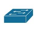
Figure1. SWITCH
Another symbol that can be seen on some older network diagrams is for a bridge; a bridge is a device that also forwards frames only at Layer 2; however a bridge predated switches and typically only had a few interfaces at most and was used to create separate collision domains. The symbol is shown in

FIGURE 2:bridge
Another form of a bridge that is more commonly seen these days is one that utilizes a wireless link to ‘bridge’ across a space that is not wired or is not easily wireable; this device is called a wireless bridge. The symbol used for a wireless bridge is shown in Figure 3.
X
Figure 3.:wireless bridge
A more modern version of a switch that is being more popular and thus more often seen in newer diagrams is a Layer 3 switch. A Layer 3 switch also handles Layer 2 frames like a ‘normal’ switch but also has the capability to process packets at Layer 3.The symbol for a Layer 3 switch is shown in Figure 4.

Figure 4 Layer 3 Switch
There are also a number of different devices that are not specific to a data network; one of these is an Integrated Services Digital Network (ISDN) switch. The symbol used for an ISDN switch is shown in Figure 5.

Figure 5 ISDN Switch
Finally, the last switch type discussed in this article is used for internal voice communications within a company; this device is often a Private Branch Exchange (PBX). The symbol used for a PBX is shown in Figure 6.
Figure 6 PBX
Routers

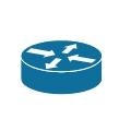
At least one router is a staple on most networks. This device is used to route any Layer 3 traffic (network) off of the local network onto another network, whether that be on another part of a company’s network or a simple Internet connection through DSL or Cable. The symbol used for a wired router is shown in Figure 7.
Figure 7 Router (Wired)
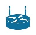
Another symbol which is commonly seen on modern networks is one that combines the capabilities of a router and a wireless access point; this device is commonly referred to as a wireless router. The symbol for a wireless router is shown in Figure 8.
Figure 8 Wireless Router
Another feature that is commonly combined with a router is voice; as with the wireless router there is a symbol that is used specifically for routers that also have voice capabilities; this symbol is shown in Figure 9.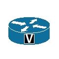
Figure 9 Voice Router
Miscellaneous
There are a number of different popular symbols that fit into different categories; for the sake of this article we will throw them all into the same heading. The first of these is a generic PC; the symbol is shown in Figure 10.

Figure 10 PC
A common symbol on network diagrams that show connections with untrusted networks is a firewall; there are a number of different variations on a firewall symbol with the one shown here being a generic firewall. An image of something resembling bricks is often part of device symbols which combine function (i.e. IOS firewall). The symbol used for a generic firewall is shown in Figure 11.
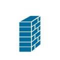
Figure 11 Firewall
The last symbol that will be shown is for a voice telephone; with voice being more and more a part of a converged network, it is becoming more common for network diagrams to include both the data network elements and the voice network elements (as these services are being combined). The symbol used for a phone is shown in Figure 12.

Figure 12 Phone
An older device that is found on network diagrams is a hub; a hub is not typically seen that often on any modern networks, as most have been replaced by switches. The symbol for a hub is shown in Figure 13.

Figure 13 Hub
Network Diagram Connectors
There are a number of different ways that connections can be shown within a diagram; generally speaking, there are four major ways to show connections. The first of these is a simple line, as all people are familiar with what a line looks like an image is not required. A line can signify any technology and the type of link typically relies on the devices being connected and/or text that are commonly combined with the line.
The second of these is a comm. link or WAN link; these connectors are used to signify that a connection is a WAN technology. For example, the link could be Frame Relay, ATM, MPLS or a number of different WAN technologies; again, the specific type of link is derived from the types of devices being connected and any accompanying text. The symbol used for a comm./WAN link is shown in Figure 14.

Figure 14 WAN Link
Another common symbol that is used in combination with other connector types is that for a ‘cloud’; the ‘cloud’ can represent a number of different things including the Internet, a Frame Relay network, and a provider’s network, among others. A symbol for a ‘cloud’ is shown in Figure 15.
Figure 15 Cloud
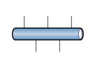
The last symbol that will be discussed is for an Ethernet network; this symbol is often used in more detailed Ethernet diagrams to represent specific Ethernet segments. The symbol for an Ethernet network is shown in Figure 16.
Network Diagram Creation and Interpretation
Figure 16 Ethernet Network
As a network engineer, there will be a number of different times that a network diagram will be used to offer a layout of how the network is constructed and connected together. The knowledge of how to create and interpret these diagrams is vital in a number of different circumstances. This article is intended to be a primer on network diagrams, what the common symbols are, how the symbols are connected and how to interpret the different connectors on a diagram.
There are certainly a number of different things that a new network engineer needs to learn before being considered experienced. One of the most underrated skills is the ability to both create and understand network diagrams. As a network engineer, there will be a number of different times that a network diagram will be used to offer a layout of how the network is constructed and connected together. The knowledge of how to create and interpret these diagrams is vital in a number of different circumstances. One common task performed by new engineers is to troubleshoot reported issues; if these issues are related to the network, it is vital that an engineer look at the existing network diagrams and understand how traffic traverses the network. Any well-managed organization typically has a number of different diagrams that show everything from high level network connectivity to logical assignment diagrams showing the assigned IP addresses (or future assignments) on the network devices or segments. This article is intended to be a primer on network diagrams, what the common symbols are, how the symbols are connected and how to interpret the different connectors on a diagram.
Network Diagram Symbols
There are a number of different symbols that are common to network diagrams; on top of these common symbols there are some unique symbols that are created as different technologies evolve. This article takes a look solely at the most common symbols used; once these symbols become familiar, any new symbols that are encountered should be easy to interpret.
Bridges and Switches
There are a number of different devices that have the word switch in their name. These devices may have different functions but they are generally related with Layer 2 (data link) of the OSI network model. This can cause some confusion as some of these devices are not restricted on modern equipment to Layer 2, this will be discussed next.
A very common symbol is the one used for a simple Layer 2 LAN switch. This device is limited to processing frames at Layer 2; the symbol is shown in Figure 1:

Figure1. SWITCH
Another symbol that can be seen on some older network diagrams is for a bridge; a bridge is a device that also forwards frames only at Layer 2; however a bridge predated switches and typically only had a few interfaces at most and was used to create separate collision domains. The symbol is shown in

FIGURE 2:bridge
Another form of a bridge that is more commonly seen these days is one that utilizes a wireless link to ‘bridge’ across a space that is not wired or is not easily wireable; this device is called a wireless bridge. The symbol used for a wireless bridge is shown in Figure 3.
X

Figure 3.:wireless bridge
A more modern version of a switch that is being more popular and thus more often seen in newer diagrams is a Layer 3 switch. A Layer 3 switch also handles Layer 2 frames like a ‘normal’ switch but also has the capability to process packets at Layer 3.The symbol for a Layer 3 switch is shown in Figure 4.

Figure 4 Layer 3 Switch
There are also a number of different devices that are not specific to a data network; one of these is an Integrated Services Digital Network (ISDN) switch. The symbol used for an ISDN switch is shown in Figure 5.

Figure 5 ISDN Switch
Finally, the last switch type discussed in this article is used for internal voice communications within a company; this device is often a Private Branch Exchange (PBX). The symbol used for a PBX is shown in Figure 6.
Figure 6 PBX
Routers

At least one router is a staple on most networks. This device is used to route any Layer 3 traffic (network) off of the local network onto another network, whether that be on another part of a company’s network or a simple Internet connection through DSL or Cable. The symbol used for a wired router is shown in Figure 7.
Figure 7 Router (Wired)

Another symbol which is commonly seen on modern networks is one that combines the capabilities of a router and a wireless access point; this device is commonly referred to as a wireless router. The symbol for a wireless router is shown in Figure 8.
Figure 8 Wireless Router

Another feature that is commonly combined with a router is voice; as with the wireless router there is a symbol that is used specifically for routers that also have voice capabilities; this symbol is shown in Figure 9.

Figure 9 Voice Router
Miscellaneous
There are a number of different popular symbols that fit into different categories; for the sake of this article we will throw them all into the same heading. The first of these is a generic PC; the symbol is shown in Figure 10.

Figure 10 PC
A common symbol on network diagrams that show connections with untrusted networks is a firewall; there are a number of different variations on a firewall symbol with the one shown here being a generic firewall. An image of something resembling bricks is often part of device symbols which combine function (i.e. IOS firewall). The symbol used for a generic firewall is shown in Figure 11.

Figure 11 Firewall
The last symbol that will be shown is for a voice telephone; with voice being more and more a part of a converged network, it is becoming more common for network diagrams to include both the data network elements and the voice network elements (as these services are being combined). The symbol used for a phone is shown in Figure 12.

Figure 12 Phone
An older device that is found on network diagrams is a hub; a hub is not typically seen that often on any modern networks, as most have been replaced by switches. The symbol for a hub is shown in Figure 13.

Figure 13 Hub
Network Diagram Connectors
There are a number of different ways that connections can be shown within a diagram; generally speaking, there are four major ways to show connections. The first of these is a simple line, as all people are familiar with what a line looks like an image is not required. A line can signify any technology and the type of link typically relies on the devices being connected and/or text that are commonly combined with the line.
The second of these is a comm. link or WAN link; these connectors are used to signify that a connection is a WAN technology. For example, the link could be Frame Relay, ATM, MPLS or a number of different WAN technologies; again, the specific type of link is derived from the types of devices being connected and any accompanying text. The symbol used for a comm./WAN link is shown in Figure 14.

Figure 14 WAN Link
Another common symbol that is used in combination with other connector types is that for a ‘cloud’; the ‘cloud’ can represent a number of different things including the Internet, a Frame Relay network, and a provider’s network, among others. A symbol for a ‘cloud’ is shown in Figure 15.
Figure 15 Cloud
The last symbol that will be discussed is for an Ethernet network; this symbol is often used in more detailed Ethernet diagrams to represent specific Ethernet segments. The symbol for an Ethernet network is shown in Figure 16.

Network Diagram Creation and Interpretation
Figure 16 Ethernet Network

No comments:
Post a Comment