Showing posts with label and. Show all posts

Tuesday, February 4, 2014

Network Security and Privacy


  1. CCNA wireless study guide and labs
  2. CCNA Networking practice guide
  3. CCNA labs
  4. CCNA Study guide 
  5. Cisco e-books
  6. E-books Network security


 University of Texax at Austin

Syllabus

  • Basics of cryptography: cryptographic hash functions, symmetric and public-key encryption
  • Authentication and key establishment
  • Buffer overflow attacks
  • Web security
  • Internet worms, viruses, spyware
  • Spam, phishing, botnets, denial of service
  • TCP/IP and DNS security
  • Firewalls and intrusion detection systems
  • Wireless security

Monday, February 3, 2014

Network Diagram Creation and Interpretation

 Figure with different nodes and edges is as follows;

As a network engineer, there will be a number of different times that a network diagram will be used to offer a layout of how the network is constructed and connected together. The knowledge of how to create and interpret these diagrams is vital in a number of different circumstances. This article is intended to be a primer on network diagrams, what the common symbols are, how the symbols are connected and how to interpret the different connectors on a diagram.

There are certainly a number of different things that a new network engineer needs to learn before being considered experienced. One of the most underrated skills is the ability to both create and understand network diagrams. As a network engineer, there will be a number of different times that a network diagram will be used to offer a layout of how the network is constructed and connected together. The knowledge of how to create and interpret these diagrams is vital in a number of different circumstances. One common task performed by new engineers is to troubleshoot reported issues; if these issues are related to the network, it is vital that an engineer look at the existing network diagrams and understand how traffic traverses the network. Any well-managed organization typically has a number of different diagrams that show everything from high level network connectivity to logical assignment diagrams showing the assigned IP addresses (or future assignments) on the network devices or segments. This article is intended to be a primer on network diagrams, what the common symbols are, how the symbols are connected and how to interpret the different connectors on a diagram.
Network Diagram Symbols

There are a number of different symbols that are common to network diagrams; on top of these common symbols there are some unique symbols that are created as different technologies evolve. This article takes a look solely at the most common symbols used; once these symbols become familiar, any new symbols that are encountered should be easy to interpret.
Bridges and Switches

There are a number of different devices that have the word switch in their name. These devices may have different functions but they are generally related with Layer 2 (data link) of the OSI network model. This can cause some confusion as some of these devices are not restricted on modern equipment to Layer 2, this will be discussed next.

A very common symbol is the one used for a simple Layer 2 LAN switch. This device is limited to processing frames at Layer 2; the symbol is shown in Figure 1:
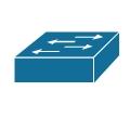


Figure1. SWITCH
Another symbol that can be seen on some older network diagrams is for a bridge; a bridge is a device that also forwards frames only at Layer 2; however a bridge predated switches and typically only had a few interfaces at most and was used to create separate collision domains. The symbol is shown in

FIGURE 2:bridge
Another form of a bridge that is more commonly seen these days is one that utilizes a wireless link to ‘bridge’ across a space that is not wired or is not easily wireable; this device is called a wireless bridge. The symbol used for a wireless bridge is shown in Figure 3.
X

Figure 3.:wireless bridge
A more modern version of a switch that is being more popular and thus more often seen in newer diagrams is a Layer 3 switch. A Layer 3 switch also handles Layer 2 frames like a ‘normal’ switch but also has the capability to process packets at Layer 3.The symbol for a Layer 3 switch is shown in Figure 4.


Figure 4 Layer 3 Switch
There are also a number of different devices that are not specific to a data network; one of these is an Integrated Services Digital Network (ISDN) switch. The symbol used for an ISDN switch is shown in Figure 5.

Figure 5 ISDN Switch

Finally, the last switch type discussed in this article is used for internal voice communications within a company; this device is often a Private Branch Exchange (PBX). The symbol used for a PBX is shown in Figure 6.
Figure 6 PBX
Routers


At least one router is a staple on most networks. This device is used to route any Layer 3 traffic (network) off of the local network onto another network, whether that be on another part of a company’s network or a simple Internet connection through DSL or Cable. The symbol used for a wired router is shown in Figure 7.
Figure 7 Router (Wired)


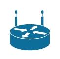
Another symbol which is commonly seen on modern networks is one that combines the capabilities of a router and a wireless access point; this device is commonly referred to as a wireless router. The symbol for a wireless router is shown in Figure 8.
Figure 8 Wireless Router

Another feature that is commonly combined with a router is voice; as with the wireless router there is a symbol that is used specifically for routers that also have voice capabilities; this symbol is shown in Figure 9.

Figure 9 Voice Router
Miscellaneous

There are a number of different popular symbols that fit into different categories; for the sake of this article we will throw them all into the same heading. The first of these is a generic PC; the symbol is shown in Figure 10.


Figure 10 PC

A common symbol on network diagrams that show connections with untrusted networks is a firewall; there are a number of different variations on a firewall symbol with the one shown here being a generic firewall. An image of something resembling bricks is often part of device symbols which combine function (i.e. IOS firewall). The symbol used for a generic firewall is shown in Figure 11.

Figure 11 Firewall

The last symbol that will be shown is for a voice telephone; with voice being more and more a part of a converged network, it is becoming more common for network diagrams to include both the data network elements and the voice network elements (as these services are being combined). The symbol used for a phone is shown in Figure 12.

Figure 12 Phone

An older device that is found on network diagrams is a hub; a hub is not typically seen that often on any modern networks, as most have been replaced by switches. The symbol for a hub is shown in Figure 13.

Figure 13 Hub
Network Diagram Connectors

There are a number of different ways that connections can be shown within a diagram; generally speaking, there are four major ways to show connections. The first of these is a simple line, as all people are familiar with what a line looks like an image is not required. A line can signify any technology and the type of link typically relies on the devices being connected and/or text that are commonly combined with the line.

The second of these is a comm. link or WAN link; these connectors are used to signify that a connection is a WAN technology. For example, the link could be Frame Relay, ATM, MPLS or a number of different WAN technologies; again, the specific type of link is derived from the types of devices being connected and any accompanying text. The symbol used for a comm./WAN link is shown in Figure 14.

Figure 14 WAN Link

Another common symbol that is used in combination with other connector types is that for a ‘cloud’; the ‘cloud’ can represent a number of different things including the Internet, a Frame Relay network, and a provider’s network, among others. A symbol for a ‘cloud’ is shown in Figure 15.
Figure 15 Cloud

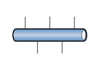
The last symbol that will be discussed is for an Ethernet network; this symbol is often used in more detailed Ethernet diagrams to represent specific Ethernet segments. The symbol for an Ethernet network is shown in Figure 16.
Network Diagram Creation and Interpretation
Figure 16 Ethernet Network

Difference between LAN and WAN

     Key Difference: LAN is a computer network that connects computers in small areas. WAN is a network that covers a broad area using private or public network transports.

The terms LAN and WAN are often confusing for people that aren’t that tech savvy. These are both connections that allow users to connect their computer to a network, including the internet. LAN is short for Local Area Network, while WAN is short for Wide Area Network. These two differ from each other in distinct ways.

 LAN is a computer network that connects computers in small areas such as home, office, school, corporation, etc. using a network media. It is useful for sharing resources such as printers, files, games, etc. A LAN network includes a couple of computer systems connected to each other, with one system connected to a router, modem or an outlet for internet access. The LAN network is built using inexpensive technologies such as Ethernet cables, network adapters and hubs. However, other wireless technologies are also available to connect the computer through a wireless access. In order to configure a LAN network, a person may also require specialized operating system software. The most popular software includes the Microsoft Windows’ Internet Connection Sharing (ICS), which allows users to create LAN.

 The first successful LAN network was created by Cambridge University in 1974 known as the Cambridge Ring; however it was not commercialized until 1976 by Datapoint Corporation. Datapoint’s ARCNET was installed at Chase Manhattan Bank in New York in 1977. The main purpose of creating a LAN was to share storage and other technologies such as printers, scanners, etc. The smallest LAN can include two computers, while the largest can, in theory, support 16 million devices according to About.com. Wikipedia states that “the larger LANs are characterized by their use of redundant links with switches using the spanning tree protocol to prevent loops, their ability to manage differing traffic types via quality of service (QoS), and to segregate traffic with VLANs.” The larger LANs also employ other devices such as switches, firewalls, routers, load balancers, and sensors.

WAN is a network that covers a broad area using private or public network transports. The best example of WAN would be the Internet, which can help connect anyone from any area of the world. Many businesses and government use WAN in order to conduct business from anywhere in the world. WANs are also responsible largely for businesses that happen across the world (i.e. a company in UK does business with a company in China). The basic definition of WAN includes a network that can span regions, countries, or even the world. However, in practicality, WAN can be viewed as a network that is used to transmit data over long distances between different LANs, WANs and other networking architectures.

WANs allow the computer users to connect and communicate with each other regardless of location. WAN uses technologies such as SONET, Frame Relay, and ATM. WANS allow different LANs to connect to other LANs through technology such as routers, hubs and modems. There are four main options for connecting WANs: Leased line, Circuit switching, Packet switching and Call relay. Leased lines are point-to-point connection between two systems. Circuit switching is a dedicated circuit path between two points. Packet switching includes devices transporting packets via a shared single point-to-point or point-to-multipoint link across a carrier internetwork. Call relay is similar packet switching but uses fixed length cells instead of variable length packets.
detailed description is available below:

LAN
WAN
Definition
LAN is a computer network that connects computers in small areas.
WAN is a network that covers a broad area using private or public network transports.
Data transfer rates
LAN offers high data transfer rates.
WAN has lower data transfer rates due to congestion
Speed
80-90 mbps
10-20 mbps
Technology
LANs use technologies such as Ethernet and Token Ring to connect to other networks.
WAN uses technologies such as MPLS, ATM, Frame Relay and X.25 for data connection over greater distances.
Bandwidth
High bandwidth is available for transmission.
Low bandwidth available for transmission.
Connection
One LAN can be connected to other LANs over any distance via telephone lines and radio waves.
Computers connected to a wide-area network are often connected through public networks, such as the telephone system. They can also be connected through leased lines or satellites.
Components
Layer 2 devices like switches, bridges. Layer 1 devices like hubs, repeaters.
Layers 3 devices Routers, Multi-layer Switches and Technology specific devices like ATM or Frame-relay Switches etc.
Problems
LANs tend to have fewer problems associated with them.
WANs have more problems  due to the large amount of system and data that is present.
Ownership
LAN networks can be owned up private companies or people that set it up at homes.
WAN are not owned up any one organization but exist under collective or distributed ownership.
Data Transmission Error
Experiences fewer data transmission errors.
Experiences more data transmission errors.
Cost
Set-up costs are low as the devices required to set up the networks are cheap.
Set-up costs are high, especially in remote locations where set-up is not done. However, WANs using public networks are cheap.
Spread
The network is spread to a very small location.
The network can be spread world-wide.
Maintenance costs
Maintenance costs are low as the area coverage is small.
Maintenance costs are high as the area coverage is world-wide.
Congestion
Less congestion
More congestion

 LANs are become more and more common in many places such as offices, corporations, homes, etc. A main reason for their growing popularity is that they are cheaper to instill and offer higher transfer speeds. LANs offer speeds up to 80 or 90 mbps due to the proximity of the computer systems to each other and lack of congestion in the network. In comparison, WANs can provide a speed of 10 to 20 mbps. Also LANs offer better security compared to WANs, which are more easily accessible with the people that know how to hack systems. WANs and LANs can be secured using firewalls, anti-virus and spyware softwares.


Sunday, February 2, 2014

[ COMPUTER NETWORK ] Error Detection and Correction

3.2 Error Detection and Correction

Error detection is generally cheaper (in terms of additional bits in overhead) to do than error correction. Neither are always needed, audio and video can often have some errors without noticeably affecting the perceived transmission quality. Error detection makes sense whenever the data must be absolutely reliable (an ATM cash machine transaction) or when the medium is very error prone (phone lines, wireless). Error correction is reasonable when retransmitting the data is not feasible (e.g. a probe designed to crash land on Saturn) or very expensive. Much of the current practice in error detection and correction is based on work by the mathematician Hamming. Applications include not only data transmission but data storage (e.g. use of a checksum to verify data integrity on a storage device).
3.2.1 Error Correcting Codes - Codes that allow the original data to be reconstructed in the face of incurring one or more errors. Generally the more errors that can be corrected, the larger the correcting code required (in bits).
  • Code word - A data frame generally consists of:
    • m data bits (message)
    • r code bits
    • m + r = n bit code word.
  • Hamming distance -  The number of bit positions two code words differ. 000 and 111 have a Hamming distance of 3, 101 and 000 have a distance of 2. The XOR (eXclusive OR) of two code word bits determines number of bits different. For example,
       100010
XOR 011010
       111000    Distance = 3   
A B | A xor B
0 0 |    0
0 1 |    1
1 0 |    1
1 1 |    0
    Significant in that for two codewords d distance apart, d single-bit errors can convert one to the other. For a distance of 1 a single error could convert one codeword into another, for example:
    000000 is a distance of 1 from 000001, a single error changes 000000 to 000001
What is the Hamming distance between 000000 and 111100?
    Parity Example
    No parity

      Even parity


    00   m=2, r=0, d=1
    000 valid   m=2, r=1, d=2
    01
    The change of any one
    001 invalid
    Adding parity doubles
    10
    bit results in a valid
    010 invalid
    the number of codewords, but 
    11
    codeword. No error 
    011 valid
    only half are valid. Any single bit


    can be detected.
    100 invalid
    error produces an invalid code.


    101 valid


    110 valid


    111 invalid

  • What is the odd parity for the ASCII data: 11111111 and 11111110?
  • Is data and parity bit 111100001 valid for even parity?
  • Suppose that one million bits were sent with a single parity bit for error detection. Would a 1-bit error be detected? Would all errors in two bits be detected?
  • Error correcting codes - To correct d errors requires a distance of 2d+1. d errors transform the codeword sent to one that is still one bit closer to the original than any other possible legal codes. The following codewords have a distance of 3, so a one bit error can be corrected. For example, if 000000 was sent and one error occurs, 100000 might be received. The closest codeword to 100000 is the original 000000 so could be corrected. Two errors might result in 110000 which would be closer to 111000, leading to an erroneous correction.
    Codewords for correcting a 1-bit error
    000000
    000111
    111000
    111111
  • What was sent if 000011 is received and we assume a 1-bit error occurred?
  • How many errors occurred at a minimum if 011001 is received? Can it be corrected reliably? Then what to do on receiving 000011?
  • Error correcting code construction - We want to construct an error correcting code with minimum check bits as overhead. For single bit error correction the limit for:
  • m data bits
  • r check bits
  • m+r+1 <= 2r
  • r=3 can correct one error in m=4 data bits, since m+3+1<=23 = 8, or m=4. 
  • r=4 can correct one error in m=11 data bits, since m+4+1<=24 = 16, or m=11. 
  • r=5 can correct one error in m=26 data bits, since m+5+1<=25 = 32, or m=26. 
The following is an example of a method by Hamming for constructing a minimal single bit error correcting code. The code has m=4 data bits, thus can encode 16 data values (00002-11112), and r=3 check bits. There are seven bits numbered from 1 to 7 with four data bits (m3, m2, m1, m0) and three check bits (p2, p1, p0). Note that check bits are placed at positions numbered as a power of 2 (e.g. check bit p2 is at position 4 = 22) between data bits. Data bits can be in any order but below are arranged in standard high bit at left order. The m data (m3m2m1m0) and r check bits (p2p1p0) are then organized into a vector as follows:
POSITION 1 2 3 4 5 6 7
BIT  p0  p1 m3 p2 m2 m1 m0
Data bits are checked by check bits whose position sum is equal to the position of the data bit. In this example:
m3 = p0 + p1            Position of m3 = Position of p0 + Position of p1 = 3
m2 = p0 + p2              Position of m2 = Position of p0 + Position of p2 = 5
m1 = p1 + p2              Position of m1 = Position of p1 + Position of p2  = 6
m0 = p2  + p1 + p0    Position of m0 = Position of p2 + Position of p1 + Position of p0 =7
    The p check bit values are computed from the data bits by forming the Exclusive-OR of all data bits checked by that bit as follows (note xor here is Exclusive OR):
    p2 = m2 xor m1 xor m0 
    p1 = m3 xor m1 xor m0
    p0 = m3 xor m2 xor m0
    Note that the sender computes p0, p1, p2.
    For example: p2 = m2 xor m1 xor m0 = 1 xor 0 xor 0 = 1
    The receiver can then perform the same calculation for the p check bits and if any differ a transmission  error occurred.
    Error position vector: The binary representation of the error position is given by the vector (C2, C1, C0), where:
    C0 = p0 xor m3 xor m2 xor m0

    C1 = p1 xor m3 xor m1 xor m0

    C2 = p2 xor m2 xor m1xor m0
    Note that the receiver computes C0, C1, C2.
    From the above computation of p2 = 1 and
    no errors in p2, m2, m1, m0
    C2 = p2 xor m2 xor m1xor m0 = 1 xor 1 xor 0 xor 0 = 0

    Example: The sender would compute the check bits and transmit both data and check bits as in the vector above. The receiver would compute the error position vector using the received data and check bit vector. For example, to send data 11002 the vector transmitted would be 01111002. Should a one bit error occur in position 4 the received vector would be 01101002.
POSITION 1 2 3 4 5 6 7
BIT  p0  p1 m3 p2 m2 m1 m0
TRANSMIT 0 1 1 1 1 0 0
RECEIVED 0 1 1 0 1 0 0
Computing the error vector yields (1, 0, 0) indicating that POSITION 4 (410 = 1002 of the received frame is in error and should be inverted to correct the error. 
    C0 = 0 xor 1 xor 1xor 0 = 0
    C1 = 1 xor 1 xor 0 xor 0 = 0
    C2 = 0 xor 1 xor 0 xor 0 = 1
3.2.2 Error Detecting Codes - To detect d errors requires a distance of d+1, no d number of  errors can change a valid code into another valid code.
    Parity
    The ASCII code uses 8 data bits, so that all possible valid 8-bit codes are used. The distance is one, since each valid code is 1 bit from another valid code. Hence one error transforms any valid code to another valid code.
    ASCII code with parity, 8 data bits and 1 bit parity for error checking has a distance of two, meaning each valid code + parity is at least 2 bits different from any other valid code. All valid codes are transformed by a 1 bit error into an invalid code. The invalid code is detected as an error.
    Using even parity (there is an even number of 1 bits in the data and parity bit) the letter A=00100001 0 (the last bit is parity calculated by the sender). A 1-bit error anywhere in data or parity will transform the codeword to an invalid code. Suppose the parity is changed from 0 to 1, then the received code is 00100001 1. The receiver calculates the parity and recognizes the codeword to be invalid so an error occurred somewhere in the data or parity.
    Note that more than one error has only a 50% chance of detection. For 11110000 0 sent, two errors could produce 11000000 0 which is still a valid code and would not be detected as an error by the receiver. Three errors producing 10000000 0 would be detected. Four errors producing 11000011 0 would not, etc. An odd number of bit errors is detected.
It is generally cheaper to detect an error and retransmit data than to send error correcting codes.
Sending 1,000,000 data bits in frames of 1000 bits using error correcting Hamming codes requires 10 check bits per 1000 data bit frames or 10,000 extra bit to correct single bit errors, a total of 1,010,000 bits transmitted (i.e. m+r+1 <= 2r or 1000+10+1=1011<= 210=1024).
  • Alternatively, 20 check bits could correct a 1 bit error for 1,000,000 data bits for a total of 1,000,020 bits (i.e. m+r+1 <= 2r or 1,000,000+20+1<= 220=1,048,576). Why is this a bad idea?
  • A single parity bit can detect one error in a 1,000,000 bit message but the message would be retransmitted when an error was detected. Under what conditions is this a bad idea or a good idea?
Using error detection and retransmit on a detected error requires 1 parity bit per 1000 data bits or 1000 check bits for the data plus 1 additional check bit for the 1000 parity bits, a total of 1,001,001 bits transmitted error free. For 1 error per million bits, error detection and retransmit requires 1,002,002 bits to be transmitted (i.e. an additional 1001 bits retransmitted).
One key problem is the lack of robustness to error detection using parity as it can detect 100% of single bit errors but only 1/2 of more than 1 bit errors. This can be improved by observing that most errors occur in bursts and reorganizing how blocks of data are sent.
Suppose that we send two 3 bit numbers 101 and 001 with even parity, 1010 and 0011. Sending as 1010 0011, a two bit error burst might transform the underlined bits to 1100 0011 which is not detected as an error by a parity check bit. Instead of sending all of one message data bits and parity bit at once which can only detect a one bit error, a more robust approach sends the first bit of each message, then the second, etc. This provides error detection of a 2 bit burst since only one bit in each column would be changed but not any 2 bit error, better than before but not good enough. The data and parity of both is sent as:
 
10  First bit
00  Second bit
11  Third bit
01  parity
Sending 1010 0011 would be transmitted as: 10001101. A two bit error burst in the underlined bits would be received as 10111101.
A two bit error burst, such as in the underlined bits, would be detected by the parity bits when the message was reconstructed by the receiver. In general, n frames with a parity bit can detect a single n bit error burst.
  •  Polynomial codes - CRC (cyclic redundancy check) codes can be constructed that provide significantly better error detection than parity. The sender computes a checksum sent with the data. The receiver recomputes the checksum on the received data using the same method, if the received and computed checksums differ, an error has been detected, retransmit the data. 
  • The method is roughly based on:
    1. Divide the data by an agreed upon divisor, the remainder is the checksum.
    2. Transmit the data and checksum remainder.
    3. Divide the received data by the agreed upon divisor. The computed and received remainder should be equal.
  • The method is straightforward and is illustrated below by an example.
    1. Convert data to binary: 'a'=61h=01100001
      M(x)=0x7+1x6+1x5+0x4+0x3+0x2+0x1+1x0 = 01100001
    2. To compute checksum, divide data M(x) by a selected generator polynomial G(x). Append 0 bits to M(x) for the degree of G(x).
      G(x)=x4+x+1 = 10011
      xrM(x) = 01100001  0000                M(x)          xr
    3. Divide xrM(x) by G(x) to get checksum, the remainder R(x). Use Exclusive OR rather than binary subtraction where a divisor divides the dividend if the same number of bits.
               Q(x) 
      G(x)/    T(x) 
               R(x)= 1110

                 1101010
      10011/011000010000
         xor 10011
              10110
          xor 10011
                10110
            xor 10011
                  10100
              xor 10011
                    1110 R(x)
      
    4. The message to be transmitted, T(x), consists of the data and checksum:  
          T(x) = xrM(x) xor R(x)
              xrM(x)          011000010000
          xor   R(x)      xor 000000001110
                T(x)          011000011110
      Note that the exclusive OR operation is effectively subtraction so the dividend T(x) is 011000010000 - 1110, what is left over is divisible by G(x). Example: 123/10 has remainder 3. (123-3)/10 has 0 remainder.
       
    5. The receiver recomputes the checksum of T(x), the remainder is 0 when no errors detected, again because after subtracting the remainder from the dividend to form T(x), T(x) is divisible by G(x).
                 1101010
      10011/011000011110
        xor  10011
              10110
          xor 10011
                10111
            xor 10011
                  10011
              xor 10011
                      00
                      00
                       0 remainder implies no error
  • CRC generator selection - Selected for robustness of error detection. For example, G(x) with x+1 as a prime factor detects all odd numbers of errors. Three polynomials are international standards, one is:
                CRC-12 = x12+x11+x3+x2+x+1 = 1100000001111

Purpose and function of network device

Here are the list of the  network devices :

* Hubs
* Switches
* Routers
* Access Points
* Hardware firewall devices
These are the devices that make up the network itself.

Client Devices:

* Desktop and laptop computers
* Tablets
* Smart Phones
These are the devices that the network exists for, the devices that access the network and utilise it.

 service devices:

* Printers
* Servers
* Storage units
These are the focus of the network, the devices the users are trying to access.

Hub:

  • First we have the hub. Don’t see many of these, and I’ve never seen one in production use! A good place to start then. A hub is basically a repeater, like a parrot, everything it hears, it repeats. Any data in to any port is immediately sent out of all other ports. This means that each port on a hub is within the same segment, and collisions are more and more likely with more ports.
  •  1 segment, 1 collision domain.
  • using hub for connectivity creates the traffic congestion

Switch:


  • Next the switch. A switch starts off like a hub, but for every request it receives, it remembers the MAC address of the requester, and the port the request came in on. That way, once a request destined for that MAC is seen, it only needs to be sent out of one port, not many. This effectively makes each port into it’s own collision domain. We are still at layer two though, still on the same IP subnet, so still at one segment.
  • 1 segment, many collision domains.


Router:

  • Routers work at the level above switches, effectively moving packets based on IP address, rather than MAC address. This makes each port on a router a separate segment, and by virtue of that a separate collision domain.
  •  many segments, many collision domains.
  • routers are used to connect networks together and route packets of data from one network to another
  • Breaking up a broadcast domain is important because when a host or server sends a network broadcast, every device on the network must read and process that broadcast—unless you’ve got a router. When the router’s interface receives this broadcast, it can respond by basically saying, “Thanks, but no thanks,” and discard the broadcast without forwarding it on to other networks. Even though routers are known for breaking up broadcast domains by default, it’s important to remember that they break up collision domains as well. There are two advantages of using routers in your network:
  • They don’t forward broadcasts by default.
  • They can filter the network based on layer 3 (Network layer) information (e.g., IP address).
Four router functions in your network can be listed as follows:
  • Packet switching
  • Packet filtering
  • Internetwork communication
  • Path selection


AP:

  • Access points are effectively hubs for wireless devices. Using the shared medium of the same “channel” of the spectrum each client device shares the bandwidth of the access point.
  • 1 segment, 1 collision domain.

Firewall:
  •   firewall is a software or hardware-based network security system that controls the incoming and outgoing network traffic by analyzing the data packets and determining whether they should be allowed through or not, based on applied rule set. 
  • Firewalls can be defined in many ways according to your level of understanding. 
  • A firewall establishes a barrier between a trusted, secure internal network and another network (e.g., the Internet) that is not assumed to be secure and trusted.
  • Many personal computer operating systems include software-based firewalls to protect against threats from the public Internet. 
  • Many routers that pass data between networks contain firewall components and, conversely, many firewalls can perform basic routing functions.