Showing posts with label of. Show all posts

Monday, February 3, 2014

List of OSI protocal

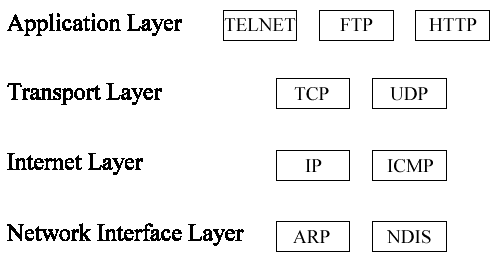
Layer 2 protocols (Data Link Layer)


    ARCnet Attached Resource Computer NETwork
    CDP Cisco Discovery Protocol
    DCAP Data Link Switching Client Access Protocol
    Distributed Multi-Link Trunking
    Distributed Split Multi-Link Trunking
    Dynamic Trunking Protocol
    Econet
    Ethernet
    FDDI Fiber Distributed Data Interface
    Frame Relay
    ITU-T G.hn Data Link Layer
    HDLC High-Level Data Link Control
    IEEE 802.11 WiFi
    IEEE 802.16 WiMAX
    LACP Link Aggregation Control Protocol
    LattisNet
    LocalTalk
    L2F Layer 2 Forwarding Protocol
    L2TP Layer 2 Tunneling Protocol
    LAPD Link Access Procedures on the D channel
    LLDP Link Layer Discovery Protocol
    LLDP-MED Link Layer Discovery Protocol - Media Endpoint Discovery
    PAgP - Cisco Systems proprietary link aggregation protocol
    PPP Point-to-Point Protocol
    PPTP Point-to-Point Tunneling Protocol
    Q.710 Simplified Message Transfer Part
    Multi-link trunking Protocol
    RPR IEEE 802.17 Resilient Packet Ring
    SLIP Serial Line Internet Protocol (obsolete)
    StarLAN
    STP Spanning Tree Protocol
    Split multi-link trunking Protocol
    Token ring a protocol developed by IBM; the name can also be used to describe the token passing ring logical topology that it popularized.
    VTP VLAN Trunking Protocol

Layer 2+3 protocols


    ARP Address Resolution Protocol
    RARP Reverse Address Resolution Protocol
    ATM Asynchronous Transfer Mode
    Frame relay, a simplified version of X.25 welcome
    MPLS Multi-protocol label switching
    SPB Shortest Path Bridging
    X.25


    MTP Message Transfer Part
    NSP Network Service Part

Layer 3 protocols (Network Layer)


    CLNP Connectionless Networking Protocol
    EGP Exterior Gateway Protocol
    EIGRP Enhanced Interior Gateway Routing Protocol
    IGMP Internet Group Management Protocol
    IGRP Interior Gateway Routing Protocol
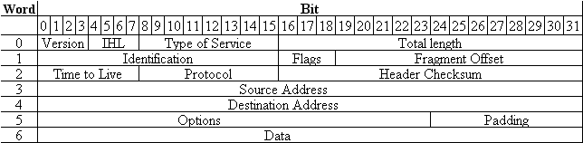
    IPv4 Internet Protocol version 4
    IPv6 Internet Protocol version 6
    IPSec Internet Protocol Security
    IPX Internetwork Packet Exchange
    Routed-SMLT
    SCCP Signalling Connection Control Part
    AppleTalk DbP

Layer 3 protocols (Network Layer management)

    IS-IS Intermediate System-to-Intermediate System
    OSPF Open Shortest Path First
    NDP Neighbor Discovery Protocol
    Gateway Discovery Protocol (GDP) is a Cisco protocol similar to IRDP
    IGRP
    EIGRP
    ICMP

L2 or L3 protocol like OSPF, BGP,ISIS, RIP,MPLS, DSL,ADSL, SDH,Sonet, DSLAM,VLAN,ATM,QoS,framerelay,

Layer 3.5 protocols

HIP Host Identity Protocol

Layer 3+4 protocol suites


    AppleTalk
    DECnet
    IPX/SPX
    Internet Protocol Suite
    Xerox Network Systems

Layer 4 protocols (Transport Layer)


    AH Authentication Header over IP or IPSec
    ESP Encapsulating Security Payload over IP or IPSec
    GRE Generic Routing Encapsulation for tunneling
    IL Originally developed as transport layer for 9P
    SCTP Stream Control Transmission Protocol
    Sinec H1 for telecontrol
    SPX Sequenced Packet Exchange
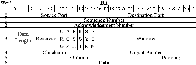
    TCP Transmission Control Protocol
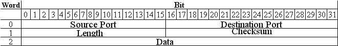
    UDP User Datagram Protocol
    DCCP Datagram Congestion Control Protocol

Layer 5 protocols (Session Layer)


    9P Distributed file system protocol developed originally as part of Plan 9
    NCP NetWare Core Protocol
    NFS Network File System
    SMB Server Message Block
    SOCKS "SOCKetS"

Other protocols

    Controller Area Network (CAN)

Layer 7 protocols (Application Layer)


    ADC, A peer-to-peer file sharing protocol
    AFP, Apple Filing Protocol
    BACnet, Building Automation and Control Network protocol
    BitTorrent, A peer-to-peer file sharing protocol
    BGP Border Gateway Protocol
    BOOTP, Bootstrap Protoc;
    CAMEL, an SS7 protocol tool for the home operator
    Diameter, an authentication, authorization and accounting protocol
    DICOM includes a network protocol definition
    DICT, Dictionary protocol
    DNS, Domain Name System
    DSM-CC Digital Storage Media Command and Control
    DSNP, Distributed Social Networking Protocol
    DHCP, Dynamic Host Configuration Protocol
    ED2K, A peer-to-peer file sharing protocol
    FTP, File Transfer Protocol
    Finger, which gives user profile information
    Gnutella, a peer-to-peer file-swapping protocol
    Gopher, a hierarchical hyperlinkable protocol
    HTTP, Hypertext Transfer Protocol
    HTTPS, Hypertext Transfer Protocol Secure
    IMAP, Internet Message Access Protocol
    IRC, Internet Relay Chat
    ISUP, ISDN User Part
    LDAP Lightweight Directory Access Protocol
    MIME, Multipurpose Internet Mail Extensions
    MSNP, Microsoft Notification Protocol (used by Windows Live Messenger)
    MAP, Mobile Application Part
    NetBIOS, File Sharing and Name Resolution protocol - the basis of file sharing with Windows.
    NNTP, Network News Transfer Protocol
    NTP, Network Time Protocol
    NTCIP, National Transportation Communications for Intelligent Transportation System Protocol
    POP3 Post Office Protocol Version 3
    RADIUS, an authentication, authorization and accounting protocol
    RDP, Remote Desktop Protocol
    Rlogin, a UNIX remote login protocol
    rsync, a file transfer protocol for backups, copying and mirroring
    RTP, Real-time Transport Protocol
    RTSP, Real-time Transport Streaming Protocol
    SSH, Secure Shell
    SISNAPI, Siebel Internet Session Network API
    SIP, Session Initiation Protocol, a signaling protocol
    SMTP, Simple Mail Transfer Protocol
    SNMP, Simple Network Management Protocol
    SOAP, Simple Object Access Protocol
    SMB, Microsoft Server Message Block Protocol
    STUN, Session Traversal Utilities for NAT
    TUP, Telephone User Part
    Telnet, a remote terminal access protocol
    TCAP, Transaction Capabilities Application Part
    TFTP, Trivial File Transfer Protocol, a simple file transfer protocol
    WebDAV, Web Distributed Authoring and Versioning
    XMPP, an instant-messaging protocol

ADVANTAGE of video over IP

ADVANTAGE of  video over IP

 I. Lower Cost of Ownership:


Networked video systems can be smart business decisions for numerous reasons:

First, since coaxial cabling isn’t used for the connections, there may be less chance of attenuation (loss of power) due to conditions such as bending, moisture and age. 
Second, a networked video system connects via Ethernet or LAN network which typically already exists in buildings with Internet access. It also means extra coax cable may not have to be installed whenever newhardware is added. In cases where additional Ethernet wiring is needed, it can be less expensive to installand uses newer technology.
Third, the modular design of a networked video system provides business benefi ts, such as scalability and fl exibility. The entire system is built on a modular grid which helps allow for multiyear security systemexpansion plans and budgetary fl exibility.
Fourth, the use of IP technology may help minimize video network downtime by providing the option for purchasing COTS (commercial off the shelf) hardware, such as computer hard drives, servers and other components, from local computer retailers.

2. “Future-Proof” IP System Technology: 

Purchasing a networked video system platform can be more “future-proof” than other platforms. An IP system can be more easily upgraded because IP technology is more than just a “black box.” The IP platform is unique in permitting both software and hardware upgrades to be completed without worrying about integration issues with older cameras. Of equal signifi cance is the ability of the NVS to allow upgrades while the network is running and without the hassle of scheduling downtime for updates.The ability to upgrade software and other applications when necessary, add new hardware when needed and to integrate legacy cameras can help provide the end user with an opportunity to utilize their same  video surveillance security system for many years.

3. Improved Management Capabilities: 

The Network Video Recorder (NVR) operates like a command center for the entire system, providing more m control and making modifi cations easier. The management capabilities of an NVR include the use of  more consistent digital technology, the ability to effi ciently redirect video feeds when a server goes down,
 he functionality to manage high-traffi c times and the fl exibility to view video feeds from anywhere withan Internet connection.
A standard functionality of an NVR includes complete redundancy capabilities, which means when a server goes down, security video feeds can be redirected to a new destination server. The term “digital” is commonly used to describe functionality for both the DVR and NVR. However, it is how and where digitization is applied that is the key differentiator between the recording technologies.  An NVR receives digital video feeds from cameras via an Ethernet or LAN network and uses digital technology to compress and store them on a hard drive. In contrast, a DVR receives analog video feeds via a coax cable and then uses digital technology to compress and store them on a hard drive. Therefore, on a DVR, digital technology is not used in the transmission of the images but rather only in the compression and storage of the images. In addition, because the DVR uses only its internal hard drive to compress and store video, it leaves the entire system vulnerable to a hard drive failure. This is referred to as a “single-point-of-failure” which is a common problem with single port encoder DVRs. In contrast, an IP video system is distributed across the network meaning the entire system isn’t vulnerable if something happens to the NVR.  A networked video system is also an effi cient tool for managing network high-traffi c times. Networked cameras can be viewed at one rate as on a matrix system and recorded at a different rate. Simply stated, cameras can be programmed to use less of the network’s bandwidth without altering the image quality needed for viewing. In terms of security management, the Internet has dramatically changed the way owners and managers can coordinate security operational functions. The use of IP technology allows images to travel over the Internet and remain consistent, regardless of the distance traveled. This means a remote viewer can have the ability to see video of the same quality as they would if they were onsite. Networked video systems permit live video feeds, events and analytics to be viewed anywhere with an Internet connection. In turn, this provides management teams with the agility to respond faster and more effectively to security events and still have the fl exibility to leave the premises.

4. Reduced Bandwidth for Compression, Transmission and Storage: 

For all video systems, image compression, transmission and storage require the most bandwidth. Compressing images, especially before transmission, helps minimize network bandwidth requirements, lets transmissions travel faster over a network and can allow video feeds to be stored more effi ciently. In addition, to accommodate network high-traffi c times, networked video users have the fl exibility to modify image compression specifi cations as well as size and frame rates without affecting image quality. Simply stated, when necessary, network cameras have the functionality to be viewed at one rate (30 fps NTSC/  25 fps PAL) as on a matrix system, and recorded at a different rate (from 1-30 NTSC/1-25 PAL fps per camera). Video over IP systems use a more effective compression protocol than traditional systems. Traditional systems video is converted to digital imagery at the DVR and then compressed for storage. This means the DVR hard drive has to handle all conversions, compressions and storage. Whereas, IP-based systems distribute these functions throughout the network putting signifi cantly less stress on the recorder. In addition, some newer network cameras have built-in functionality to compress images before video feeds are released to the network. In terms of storage, IP video network storage can be more effi cient than traditional systems. As part of the NVR functionality, video feeds can automatically be moved to a storage area network (SAN) at predetermined times or manually when space is needed. In contrast, a traditional DVR hard drive serves
as the main storage component and typically has limited capacity. Video clips that are needed for
 extended periods of time must manually be moved to a SAN, external hard drive or burned to a DVD. Each of these latter storage options requires personnel to handle the data transfer and can be cumbersome, time-consuming and provides fi le corruption opportunities.

FUNCTION OF TCP LAYER


The TCP/IP model was not created by a standards developing committee but rather from research funded by the Department of Defense (DOD) Advanced Research Projects Agency (ARPA). ARPA begin working on TCP/IP technology in the mid 1970s with the protocols and architecture taking on their current structure in the 1977-1979 time frame.

TCP/IP Protocol Stack Layers

The TCP/IP protocol stack is organized into four layers as shown in Figure 2-3. Each of the four layers of the TCP/IP model exists as an independent module and performs a well-defined function as described later in this section. Each layer communicates and works with the functions of the layers that are immediately above and below it. For example, looking at Figure 2-3 you see that the Transport layer sits between the Application and Internet layers. This means that the Transport layer will communicate and work with both the Application and Internet layers. The Transport layer cannot communicate directly with any other layer of the TCP/IP model.

Figure 3: TCP/IP Protocol Stack

TCP/IP Application Layer

The Application layer is the highest layer in the TCP/IP model. It is used by applications to access services across a TCP/IP network. Some of the applications that operate at this layer are a Web browser, file transfer program (FTP), and a remote login program. The Application layer passes data to the next layer in the stack, the Transport layer.

TCP/IP Transport Layer

The Transport layer is located at layer 3 of the TCP/IP model. The main responsibility of the Transport layer is to provide communication from one application to another application. If several application programs are running on a computer then the Transport layer has to figure out how to control the data from each application so that it can be sent to the next lower layer correctly. The Transport layer adds the following additional information to each data packet:
The identity of the application sending the data
The identity of the application that should receive the data
A checksum
The system that receives the data uses the checksum to verify that all of the data arrived. It also uses the identity of the receiving application so it can route the data appropriately.

TCP/IP Internet Layer

The Internet layer is located at layer two of the TCP/IP model. It is responsible for handling the communication from one computer to another computer. It accepts a request to send data from the Transport layer. It accepts the data, encapsulates it in a datagram, and then uses a routing algorithm to determine the best method for delivering it. After determining the best way to route the datagram, the Internet layer passes it to the Network Interface layer.

TCP/IP Network Interface Layer

The Network Interface layer is the lowest level in the TCP/IP model. It accepts the datagram from the Internet layer and transmits it over the network. To accomplish this task the Network Interface layer must be fully aware of the network hardware that it is using. The Network Interface layer is also responsible for translating an Internet address into a hardware address.
Exam Watch: Remember the names and functions of each of the four layers of the TCP/IP model.

TCP/IP Protocol Stack Compared to OSI Layers

The TCP/IP model can be compared loosely to the OSI model as shown in Figure 2-4. The Application layer of the TCP/IP model performs the same functions as layers 5, 6, and 7 of the OSI model. The Transport layers in both models perform the same functions. The Internet layer of the TCP/IP model equates to the same functions as the Network layer of the OSI model. The Network Interface layer of the TCP/IP model compares to the functions of layers 1 and 2 of the OSI model.

Figure 4: TCP/IP Model Compared to OSI Model
Exam Watch: Remember which layers of the TCP/IP model equate to the layers of the OSI model.

TCP/IP Protocol Suite

Contained within the four layers of the TCP/IP model are several protocols that direct how computers connect and communicate using TCP/IP. Even though the protocol suite is called TCP/IP, many other protocols are available besides the TCP and IP protocols.

Identify Protocols by Layers

Each protocol can be identified with a layer of the TCP/IP model. We will examine several of the protocols available at each layer.

Application Layer

The Application layer supports both the NetBIOS interface and the Windows Sockets interface.

NetBIOS

NetBIOS over TCP/IP allows NetBIOS client and server applications to be run over the Wide Area Network (WAN). Some of the applications that are NetBIOS-over -TCP compliant are the Windows NT browser service, netlogon service, messenger service, workstation service, and server service.

Windows Sockets

Windows Sockets is a programming interface based on the "socket" interface that was originally developed at the University of California at Berkeley. Windows Sockets includes enhancements that take advantage of the message-driven characteristics of Windows. Windows NT 4.0 supports version 2.2.0, which was published in May 1996. Some of the common protocols that use Windows Sockets are telnet, ftp, and http.

Transport Layer

The Transport layer consists of two protocols, the Transmission Control Protocol (TCP) and the User Datagram Protocol (UDP). Both TCP and UDP support ports. When a program sends or receives data on a TCP/IP network, it has to connect to a port. Ports are identified in the header of both the TCP and UDP protocols. The header contains two 16-bit numbers that identify the source port and the destination port. The Transport layer examines the port numbers in the header and delivers the data to the correct port.

TCP

TCP is one of the protocols that the suite is named for. TCP provides a reliable, connection-based delivery service. Successful delivery of packets is guaranteed by the TCP protocol. It uses a checksum to ensure that data is sequenced correctly. If a TCP packet is lost or corrupted during transmission, TCP resends a good packet. The reliability of TCP is necessary for critical services, such as electronic mail. However, the reliability does not come cheaply as TCP headers have additional overhead added to them. The overhead is necessary to guarantee successful delivery of the data. Another factor to remember about TCP is that the protocol requires the recipient to acknowledge the successful receipt of data. Of course, all the acknowledgments, known as ACKs, generate additional traffic on the network, which causes a reduction in the amount of data that is passed for a given time frame.
The TCP header consists of six words of 32 bits each. The seventh word is the actual data. Figure 2-5 shows the format of a TCP header.

Figure 5: Transmission Control Protocol Header
Table 2-1 describes each of the items that are contained in the TCP header.
Name
Bit Size
Purpose
Source Port
16
The source port number.
Destination Port
16
The destination port number.
Sequence Number
32
The sequence number of the first data octet in this segment unless the SYN control bit is set. If the SYN control bit is set, then the sequence number is the initial sequence number (ISN) and the first data octet is ISN+1.
Acknowledgment Number
32
This portion of the header contains the value of the next sequence number that the sender of the segment is expecting to receive if the ACK control bit is set. Once a connection is established, this is always sent.
Data Length
4
The number of 32-bit words in the TCP header. This indicates where the data begins.
Reserved
6
Reserved for future use. It has to be zero.
Flags
6
The bits from left to right.URG: Urgent Pointer field significant
ACK: Acknowledgment field significant
PSH: Push function
RST: Reset the connection
SYN: Synchronize sequence numbers
FIN: No more data from sender
Window
16
The number of data octets beginning with the one indicated in the acknowledgment field, which the sender of this segment is willing to accept.
Checksum
16
The checksum field is the 16-bit 1’s complement of the 1’s complement sum of all 16-bit words in the header and data.
Urgent Pointer
16
This field communicates the current value of the urgent pointer as a positive offset from the sequence number in this segment. The urgent pointer points to the sequence number of the octet following the urgent data. This field is interpreted only in segments that have the URG control bit set.
Options
variable
Options may occupy space at the end of the TCP header and are a multiple of 8 bits in length. All options are included in the checksum.
Padding
variable
The TCP header padding is used to ensure that the TCP header ends and data begins on a 32-bit boundary. The padding is composed of zeros.
Table 1: Description of the Contents in a TCP Header

UDP

UDP offers a connectionless datagram service that is an unreliable "best effort" delivery. The arrival of datagrams is not guaranteed by UDP nor does it promise that the delivered packets are in the correct sequence. Applications that don’t require an acknowledgment of receipt of data use the User Datagram Protocol.
The UDP header consists of two words of 32 bits each. The third word is the actual data. Figure 2-6 shows the format of a UDP header.

Figure 6: User Datagram Protocol Header
Table 2-2 describes each of the items that are contained in the UDP header.
Name
Bit Size
Purpose
Source Port
16
The source port number.
Destination Port
16
The destination port number.
Length
16
The length in octets of this user datagram including the header and data.
Checksum
16
The checksum field is the 16-bit 1's complement of the 1's complement sum of all 16-bit words in the header and data. The checksum is an option in the UDP header and not always used.
Table 2: Description of the Contents in a UDP Header
Exam Watch: Keep in mind the key differences between the Transmission Control Protocol and User Datagram Protocol.

Internet Layer

The Internet layer consists of two protocols, the Internet Protocol (IP) and the Internet Control Message Protocol (ICMP).

IP

IP is the other protocol that the suite is named for. It is a vital link in the suite as all information that is sent using the TCP/IP protocol suite must use it. IP provides packet delivery for all other protocols within the suite. It is a connectionless delivery system that makes a "best-effort" attempt to deliver the packets to the correct destination. IP does not guarantee delivery nor does it promise that the IP packets will be received in the order they were sent. IP does use a checksum but it confirms only the integrity of the IP header. Confirmation of the integrity of data contained within an IP packet can be accomplished only through higher level protocols.
The IP header consists of six words of 32 bits each. The seventh word is the actual data. Figure 2-7 shows the format of a IP header.

Figure 7: Internet Protocol Header
Table 2-3 describes each of the items that are contained in the IP header.
Name
Bit Size
Purpose
Version
4
The format of the Internet header.
IHL
4
Internet header length is the length of the Internet header in 32-bit words. The minimum value for a correct header is 5.
Type of Service
8
An indication of the abstract parameters of the quality of service desired.
Total Length
16
The length of the datagram, measured in octets, including Internet header and data.
Identification
16
An identifying value assigned by the sender to aid in assembling the fragments of a datagram.
Flags
3
Various control flags.Bit 0: reserved, must be zero
Bit 1: (DF) 0 = may fragment, 1 = don't fragment.
Bit 2: (MF) 0 = last fragment, 1 = more fragments.
Fragment Offset
13
Indicates where in the datagram this fragment belongs. The fragment offset is measured in units of 8 octets (64 bits). The first fragment has offset zero.
Time to Live
8
Indicates the maximum time the datagram is allowed to remain in the Internet system. If this field contains the value zero, then the datagram has to be destroyed.
Protocol
8
Indicates the next level protocol used in the data portion of the Internet datagram.
Header Checksum
16
A checksum on the header only. Since some header fields change, such as the time-to-live field, this is recomputed and verified at each point that the Internet header is processed.
Source Address
32
The source address.
Destination Address
32
The destination address.
Options
variable
The options may or may not appear in datagrams. A couple of the available options are:Security: used to carry security, compartmentation, and handling restriction codes compatible with DOD requirements.
Record Route: used to trace the route an Internet datagram takes.
Padding
variable
The Internet header padding is used to ensure that the Internet header ends on a 32-bit boundary. The padding is zero.
Table 3: Description of the Contents in a IP Header

ICMP

ICMP allows systems on an TCP/IP network to share status and error information. You can use the status information to detect network trouble. ICMP messages are encapsulated within IP datagrams, so they may be routed throughout an internetwork. Two of the most common usages of ICMP messages are ping and tracert.
You can use ping to send ICMP Echo Requests to an IP address and wait for ICMP Echo Responses. Ping reports the time interval between sending the request and receiving the response. Using ping you can determine whether a particular IP system on your network is functioning correctly. There are many different options that can be used with the ping utility. These are covered in depth in Chapter 3.
Tracert traces the path taken to a particular host. It can be very useful when troubleshooting internetworks. Tracert sends ICMP echo requests to an IP address while it increments the time-to-live field in the IP header by a count of one after starting at one and then analyzing the ICMP errors that get returned. Each succeeding echo request should get one further into the network before the time-to-live field reaches 0 and an ICMP Time Exceeded error is returned by the router attempting to forward it.
Exercises 2-1 and 2-2 give you the opportunity to use both the PING and TRACERT utilities.
Exercise 2-1 Ping – to Test Communication with a Distant Computer
  1. Log on as Administrator to a system that has the TCP/IP Protocol installed and is connected to the Internet.
  2. Click the Start button and select Programs | Command Prompt.
  3. At the command prompt type PING 207.159.134.58. Was your PING successful?
  4. Try to PING some of these other IP addresses: 206.66.12.43, 165.121.81, 206.151.75.79, 199.1.11.15, 199.227.250.70. Did you PING them successfully?
Exercise 2-2 Tracert – to Trace the Route Taken to a Distant Computer
  1. Log on as Administrator to a system that has the TCP/IP Protocol installed and is connected to the Internet.
  2. Click the Start button and select Programs | Command Prompt.
  3. At the command prompt type TRACERT 207.159.134.58. How many hops did it take to arrive at your destination?
  4. Try running TRACERT on some of these other IP addresses: 206.66.12.43, 165.121.81, 206.151.75.79, 199.1.11.15, 199.227.250.70.

Network Interface Layer

The Network Interface layer not only uses the Address Resolution Protocol (ARP) but it is also the location that the Network Driver Interface Specification (NDIS) 4.0 works from.

ARP

ARP is used to provide IP address-to-physical address resolution for IP packets. To accomplish this feat, ARP sends out a broadcast message with an ARP request packet in it that contains the IP address of the system it is trying to find. All systems on the local network detect the broadcast message and the system that owns the IP address ARP is looking for replies by sending its physical address to the originating system in an ARP reply packet. The physical/IP address combo is then stored in the ARP cache of the originating system for future use.
All systems maintain an ARP cache that includes their own IP address-to-physical address mapping. The ARP cache is always checked for an IP address-to-physical address mapping before initiating a broadcast.
You can see the contents of your ARP cache by using the ARP utility. There are many different options that can be used with the ARP utility. These are covered in depth in Chapter 3. Exercise 2-3 shows you how to check the contents of your ARP cache.
Exercise 2-3 ARP – To view What Is in the Address Table
  1. Log on as Administrator to a system that has the TCP/IP Protocol installed.
  2. Click the Start button and select Programs | Command Prompt.
  3. At the command prompt type ARP -a. The entries in your cache are displayed.
Figure 2-8 shows entries in the ARP cache of my system.

Figure 8: The ARP Cache for a System

NDIS 4.0

NDIS is a standard that allows multiple network adapters and multiple protocols to coexist on the same computer. By providing a standard interface, NDIS permits the high-level protocol components to be independent of the network interface card. All transport drivers call the NDIS interface to access network interface cards.
Figure 2-9 shows a sampling of the protocols available on the four TCP/IP layers.

Figure 9: Protocols by TCP/IP Layers
Now that you know about the different protocols used by the TCP/IP layers, here is a quick reference for possible scenario questions, and the appropriate answer:
Begin Q & A
"Marissa says that it take her "forever" to reach a host in another city…" Use TRACERT to see the path her machine may be using to contact the other machine. You may be able to isolate a routing problem.
"Martha is having a problem with inconsistent data she is receiving from a network application…" It is possible that the network application uses UDP instead of TCP. Since UDP provides unreliable "best effort" delivery, some data may be lost. You need to see if you can get her an equivalent network application that uses TCP to ensure that all data she needs arrives safely.
"James from the sales department tells you that he cannot communicate with a machine in the accounting department…" You need to run the PING utility to see if the computer is operating correctly on the network.

Network Data Flow

In the previous sections, we have seen the layers that make up the OSI and TCP/IP models and the purpose of each of those layers. Now it is time to see what happens as data begins to flow from one layer to the next.

How A Message Flows Through the TCP/IP Protocol Layers

The sending process passes data to the Application layer, which attaches an application header as shown in Figure 2-10.

Figure 10: Data Passed to the Application Layer
The Application layer passes the packet to the Transport layer, which in turn adds its header to the packet as shown in Figure 2-11.

Figure 11: Application Data Passed to the Transport Layer
The Transport layer passes the packet to the Internet layer, which in turn adds its header to the packet as shown in Figure 2-12.

Figure 12: Transport Data Passed to Internet Layer
The Internet layer passes the packet to the Network Interface layer where it is actually transmitted to the receiving computer as shown in Figure 2-13.

Figure 13: Data Leaving the Network Interface Layer, Headed to the Receiving Computer
On the receiving computer, the different headers are stripped off, one by one, as the packet goes up the layers until it finally reaches the receiving process.

Sunday, February 2, 2014

Purpose and function of network device

Here are the list of the  network devices :

* Hubs
* Switches
* Routers
* Access Points
* Hardware firewall devices
These are the devices that make up the network itself.

Client Devices:

* Desktop and laptop computers
* Tablets
* Smart Phones
These are the devices that the network exists for, the devices that access the network and utilise it.

 service devices:

* Printers
* Servers
* Storage units
These are the focus of the network, the devices the users are trying to access.

Hub:

  • First we have the hub. Don’t see many of these, and I’ve never seen one in production use! A good place to start then. A hub is basically a repeater, like a parrot, everything it hears, it repeats. Any data in to any port is immediately sent out of all other ports. This means that each port on a hub is within the same segment, and collisions are more and more likely with more ports.
  •  1 segment, 1 collision domain.
  • using hub for connectivity creates the traffic congestion

Switch:


  • Next the switch. A switch starts off like a hub, but for every request it receives, it remembers the MAC address of the requester, and the port the request came in on. That way, once a request destined for that MAC is seen, it only needs to be sent out of one port, not many. This effectively makes each port into it’s own collision domain. We are still at layer two though, still on the same IP subnet, so still at one segment.
  • 1 segment, many collision domains.


Router:

  • Routers work at the level above switches, effectively moving packets based on IP address, rather than MAC address. This makes each port on a router a separate segment, and by virtue of that a separate collision domain.
  •  many segments, many collision domains.
  • routers are used to connect networks together and route packets of data from one network to another
  • Breaking up a broadcast domain is important because when a host or server sends a network broadcast, every device on the network must read and process that broadcast—unless you’ve got a router. When the router’s interface receives this broadcast, it can respond by basically saying, “Thanks, but no thanks,” and discard the broadcast without forwarding it on to other networks. Even though routers are known for breaking up broadcast domains by default, it’s important to remember that they break up collision domains as well. There are two advantages of using routers in your network:
  • They don’t forward broadcasts by default.
  • They can filter the network based on layer 3 (Network layer) information (e.g., IP address).
Four router functions in your network can be listed as follows:
  • Packet switching
  • Packet filtering
  • Internetwork communication
  • Path selection


AP:

  • Access points are effectively hubs for wireless devices. Using the shared medium of the same “channel” of the spectrum each client device shares the bandwidth of the access point.
  • 1 segment, 1 collision domain.

Firewall:
  •   firewall is a software or hardware-based network security system that controls the incoming and outgoing network traffic by analyzing the data packets and determining whether they should be allowed through or not, based on applied rule set. 
  • Firewalls can be defined in many ways according to your level of understanding. 
  • A firewall establishes a barrier between a trusted, secure internal network and another network (e.g., the Internet) that is not assumed to be secure and trusted.
  • Many personal computer operating systems include software-based firewalls to protect against threats from the public Internet. 
  • Many routers that pass data between networks contain firewall components and, conversely, many firewalls can perform basic routing functions.